The post Building hours spent first year appeared first on Bouw project G-Force1500C catamaran.
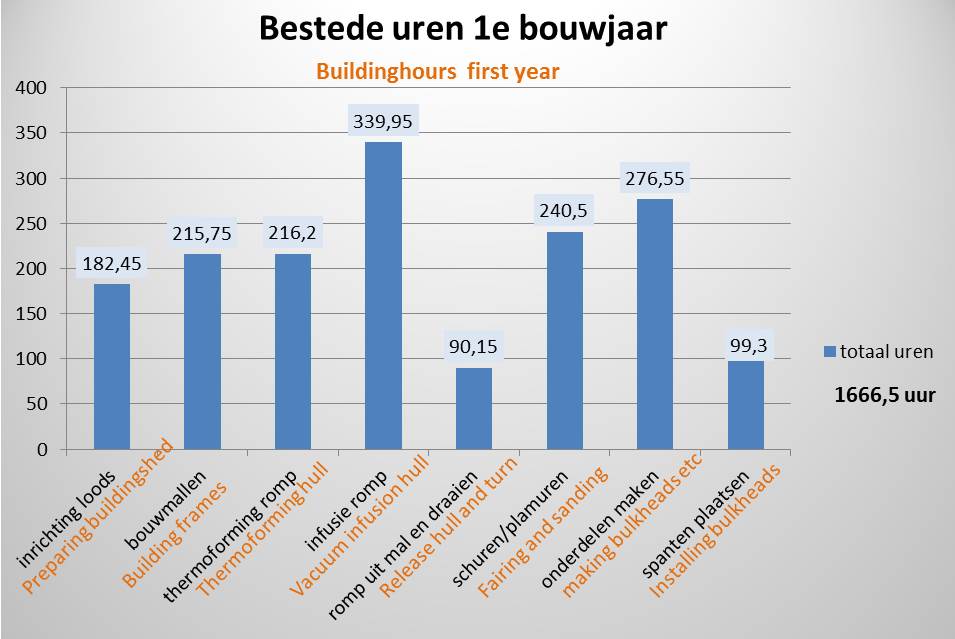
]]>A year later and 1666 building hours spent, we accomplished a lot.
The designer estimated 6000 building hours for a G-Force 1500 Cruise.
If you use a kit you probably save about 1000 building hours.
We categorized the building hours in the shed by main processes.
Beside the shed we spent a lot extra hours with discuss the details, looking for technical solutions, visiting conferences, purchase, project administration and this website of course.
Building hours
Extra info:
Preparing shed:
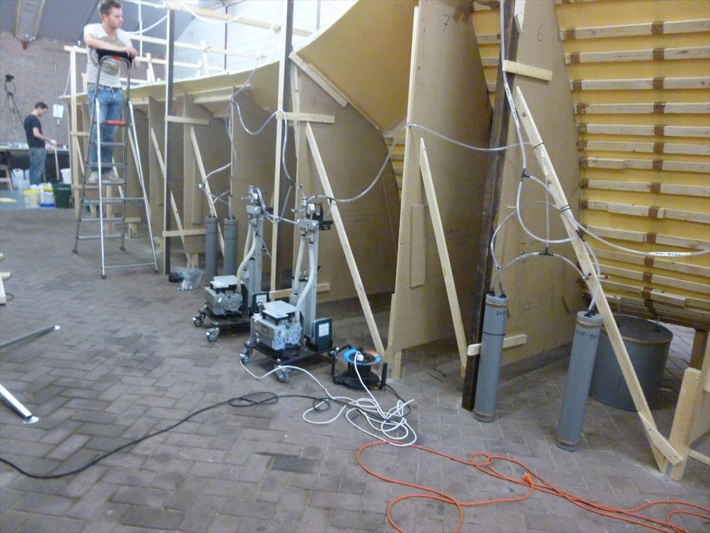
We needed a lot of small parts like glue table, workbench etc. The most time we invested in isolating the shed.
It was very worth full to be able to work with epoxy during the winter.
Even end of November we could do a big infusion project with a temperature of 21 degr.
Buildingframes:
Frames for 2 hulls, drawing, cutting and aligning.
Thermoforming hull:
Both hulls fully in foam including cutting and milling the panels.
Infusie romp:
First we spent 25 hours with a test project and air leak test on the chamfer.
We needed 125 hours for the inside port side hull (applying laminate, vacuum infusion materials, searching for leaks, infusion day and unpack afterwards).
After that we have more routine and only needed around 90 hours for the inside of the star board hull and around 90 hours for the outside of the port side hull.
Releasing hull from mold and turning 180 degr.:
Unscrew, break down, turning mold, hoisting frame, turning, clean the shed.
Fairing and sanding:
Filling the seams with micro balloons for an air tight inside hull.
Sanding the foam at the outside before infusion and coating the borders.
Start with fairing the port side hull (totaly fairing in sanding ca 130 hours)
Making bulkheads etc:
Vacuum infusion flat panels, drawing – cutting -sanding all the bulkheads and under flour web for 2 hulls.
Install bulkheads:
Bulkheads and underfloor web in both hulls, applying fillets.
The post Building hours spent first year appeared first on Bouw project G-Force1500C catamaran.
]]>The post Vacuum infusion hull out side appeared first on Bouw project G-Force1500C catamaran.
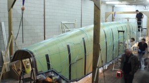
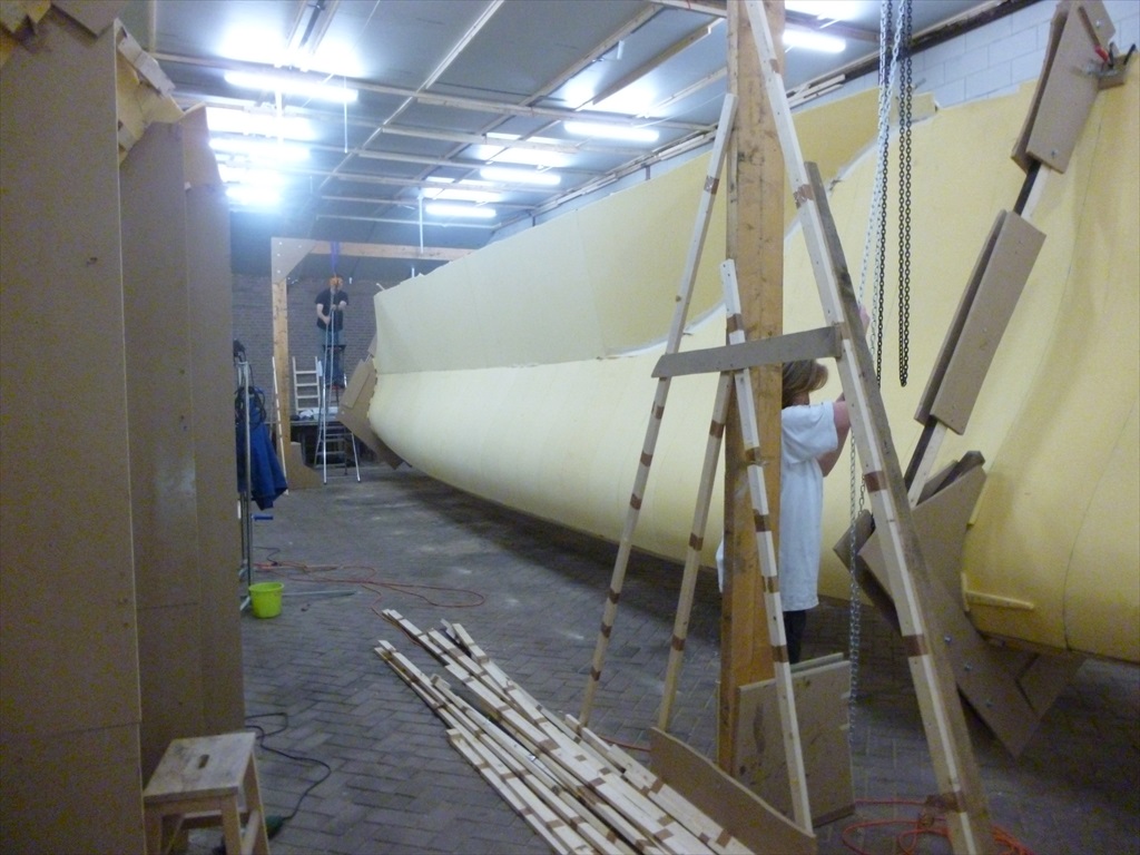
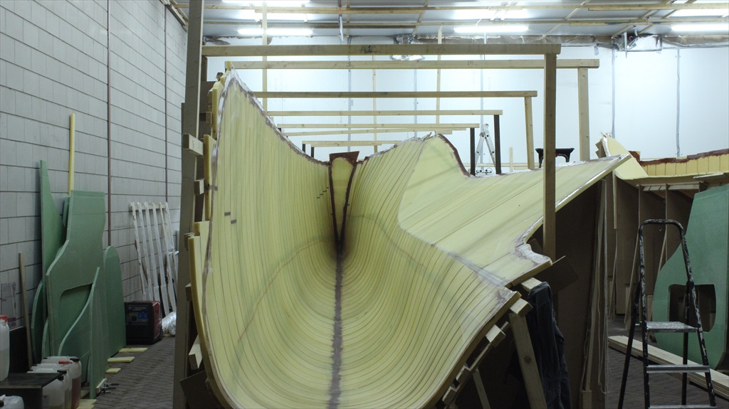
]]>After turning the hull we can start preparing the vacuum infusion for the outside of the hull. This should proceed much faster, as we don’t need any tests since the fiberglass on the inside make the hull airtight. We also know that the size of such a vacuum infusion project is no issue.
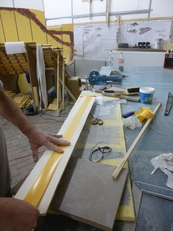
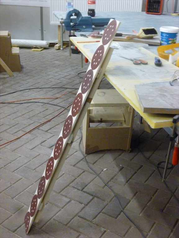
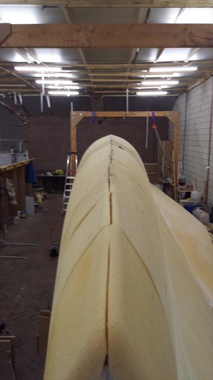
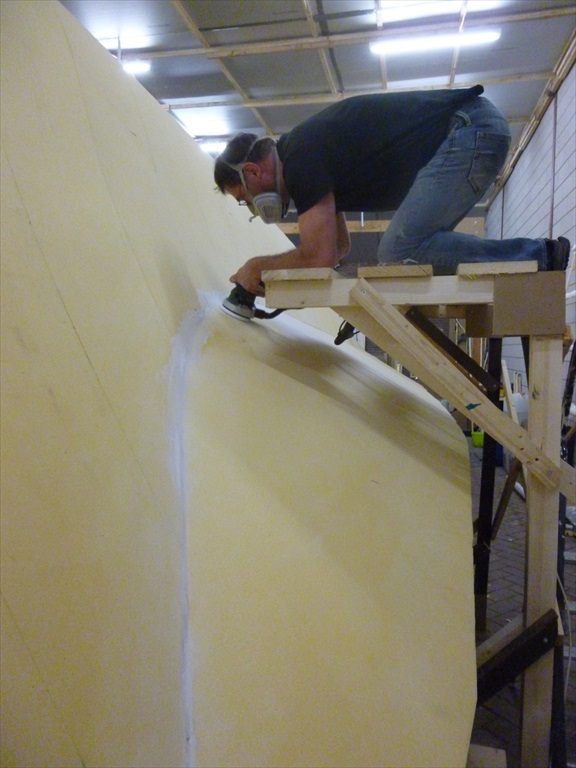
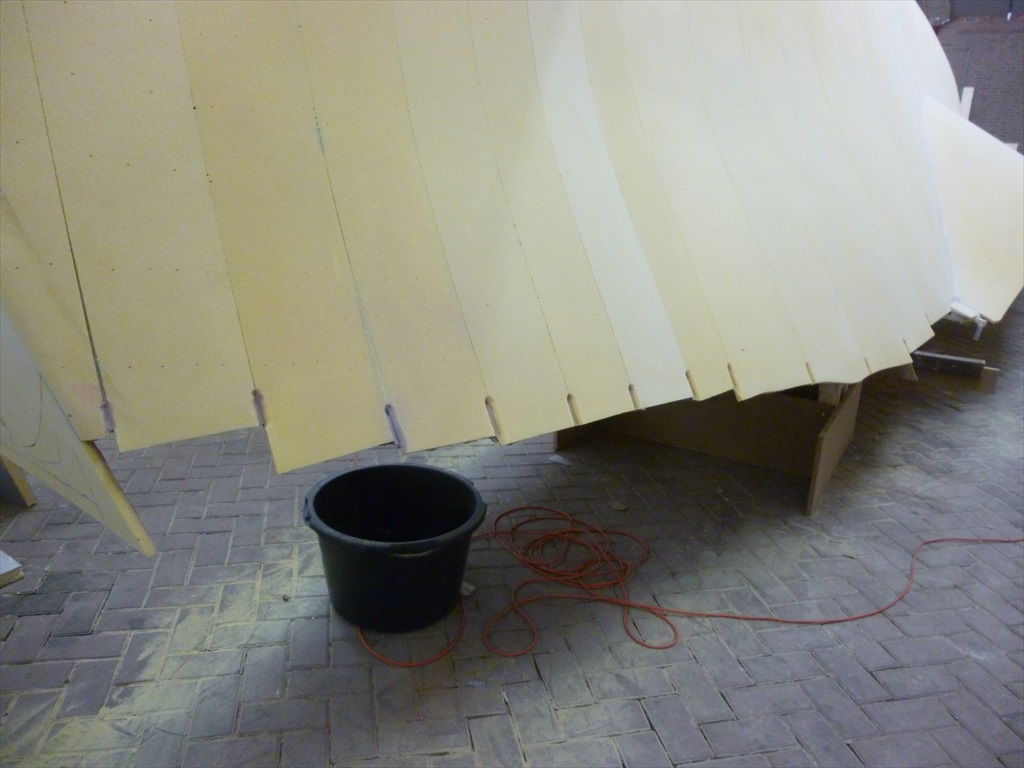
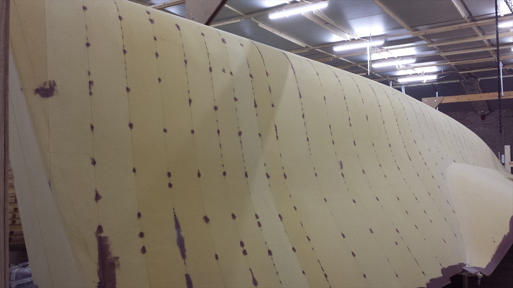
Fairing the foam hull
First, we roughly shape the bow and remove the edges with a jigsaw. Then, we fine-tune the shape of the bow with an eccentric sander.
Although the foam panels were well shaped, there were a few small height differences in the panels. Therefore, we created a batten with sandpaper out of 9 mm multiplex of approximately 1.20 meters. Double-sided tape keeps the sandpaper in place while the bar is firm enough to avoid dents in the foam and flexible enough to follow different shapes of the hull.
Within just a few hours the 65m2 foam hull is as smooth as it gets.

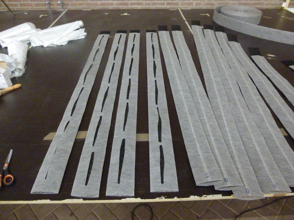
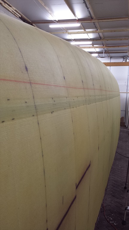
All fiberglass is again placed longitudinally and overlaps just above the water line. The bottom part contains 1400 grams (800 + 600) and the upper part contains 1250 grams (850 + 400). This results in 2650 grams of fiberglass at the overlapping section. By drawing the exact position of the overlap and milling a 1 mm band, it will be easier to place the fiberglass on exactly the right position avoiding additional filling.
The keel is always subjected to imperfections during thermoforming, but the shape of the foam is still easily improved with the eccentric sander.
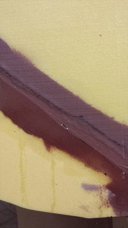
The seam with the chamfer panel is firmly glued before the infusion of the hull on the inside was started. Whilst the mould is removed, it becomes easier to optimise the glue line on the chamfer panel. Though, it still requires improvising.
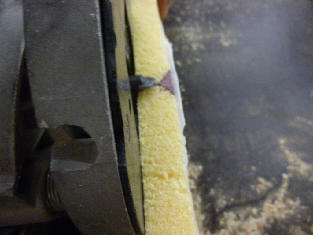
Preventing epoxy runners
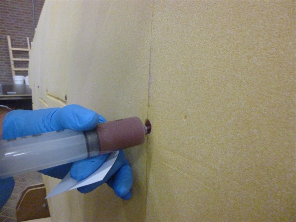
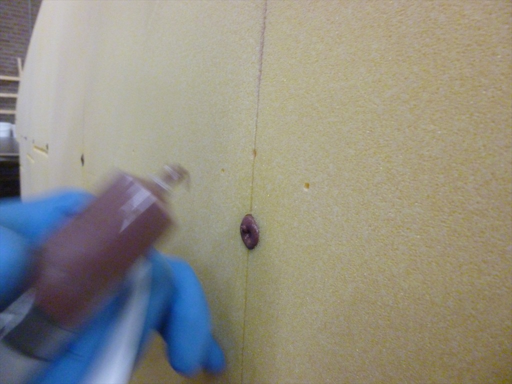
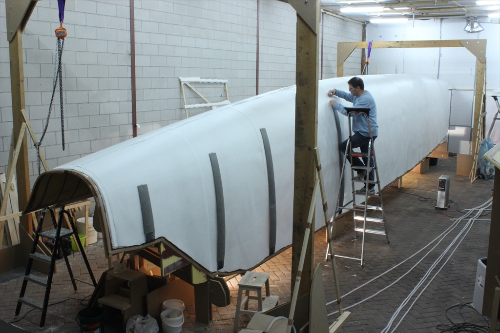
As we ensured an airtight hull during the infusion of the inside by filling all seams with micro balloons, there is no need to check this again. During the infusion of the outside all seams and holes will fill automatically with epoxy, which will run faster through these seams and holes causing “runners”. Runners will cause waste and are likely to cause air inclusions. However, by simply putting “stops” out of micro balloons at various positions, we can prevent this from happening.
By using a piece of waste to set the height of our miller, the holes will be large enough and we won’t be able to mill through the fiberglass on the inside. We can now fill the holes with micro balloons and create our “stops”. Seams at the bow are a little wider so we didn’t need to mill these.
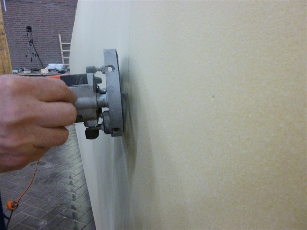
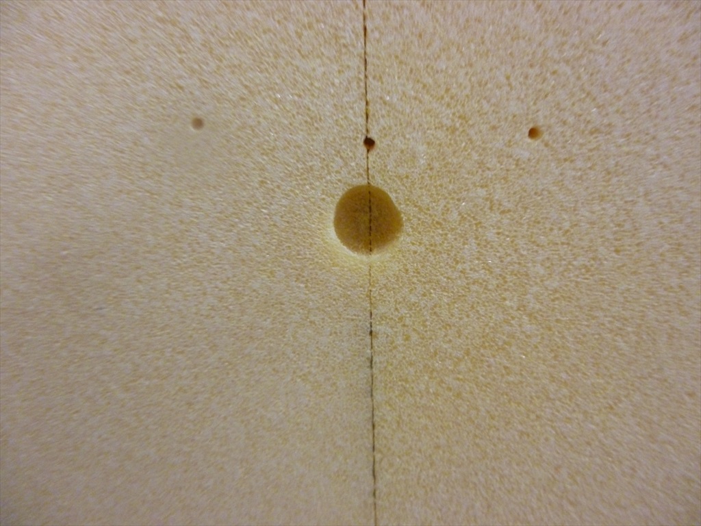
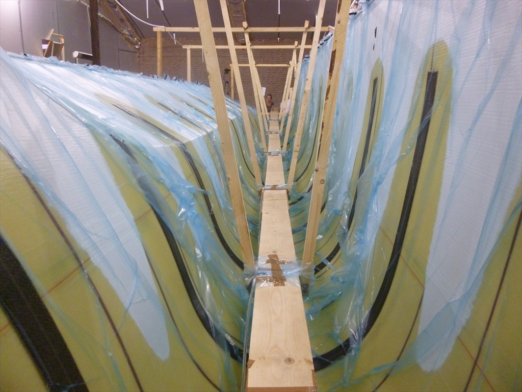
The top of the hull (currently at the bottom) is still approximately 15 cm too high so we can stick all required infusion materials on it. We also used this space during the laminating process on the inside of the hull. Therefore, there is no fiberglass on the inside of the hull meaning there is a risk of air leakage. We eliminated this risk by gently milling a small opening and filled it with micro balloons.
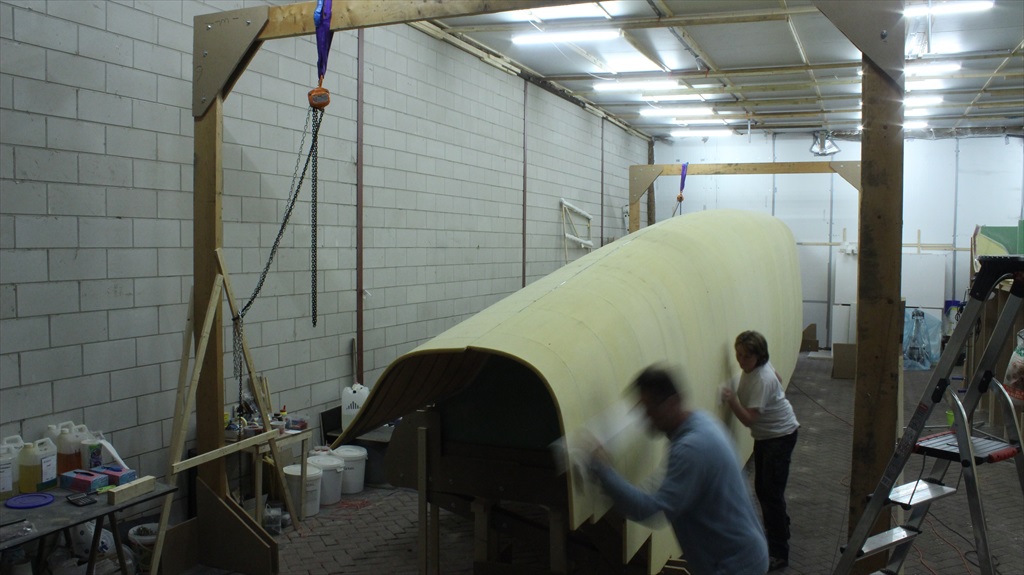
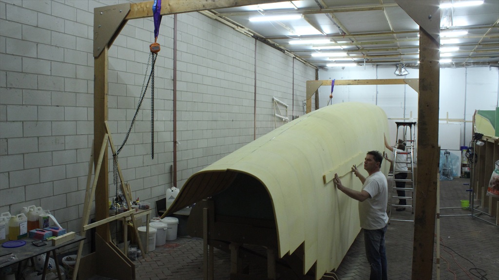
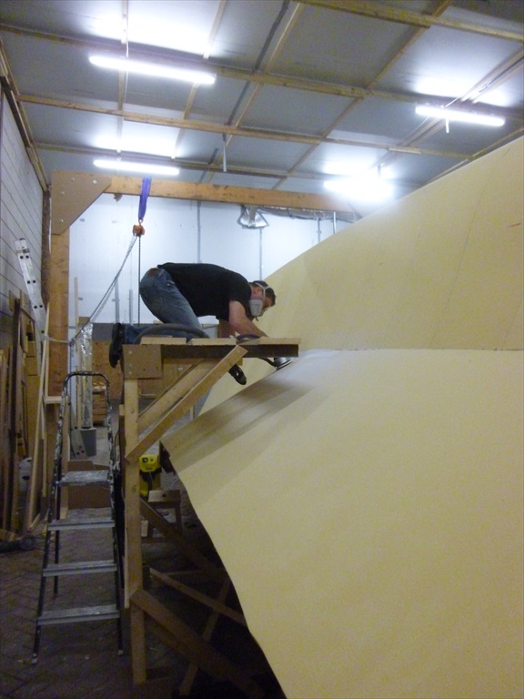
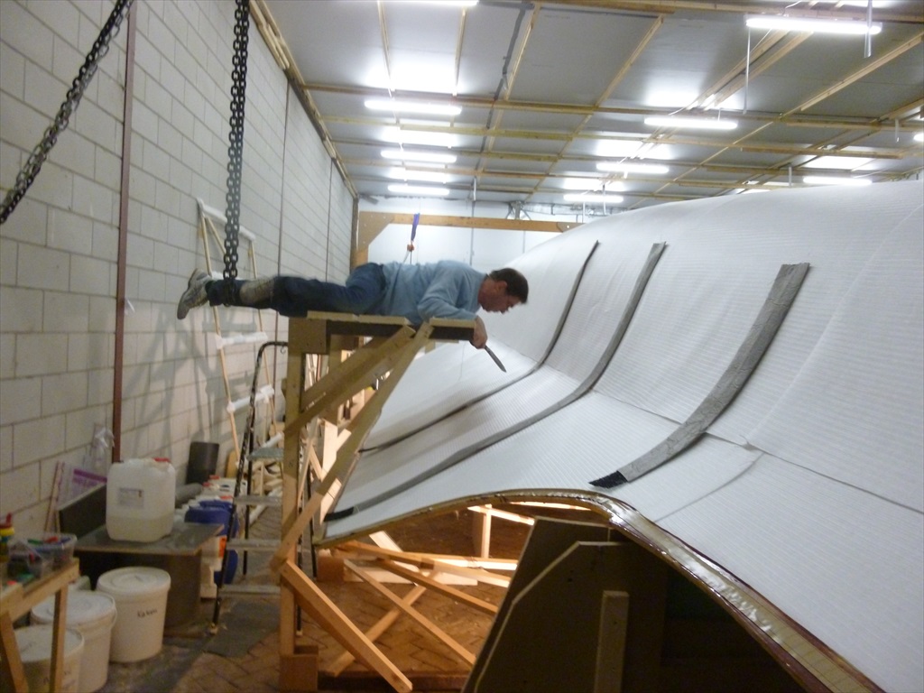
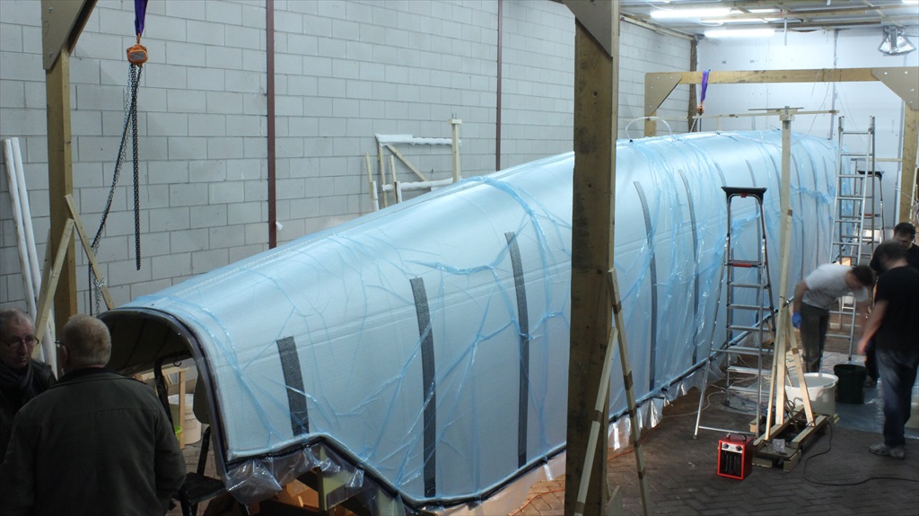
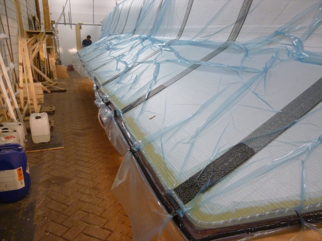
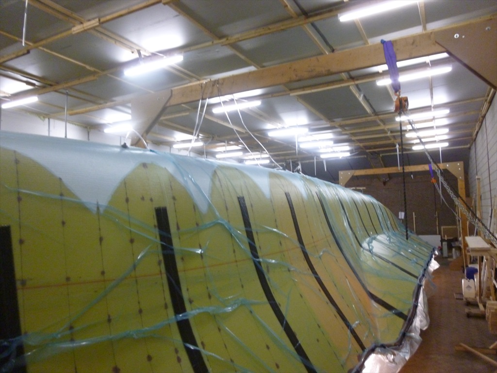
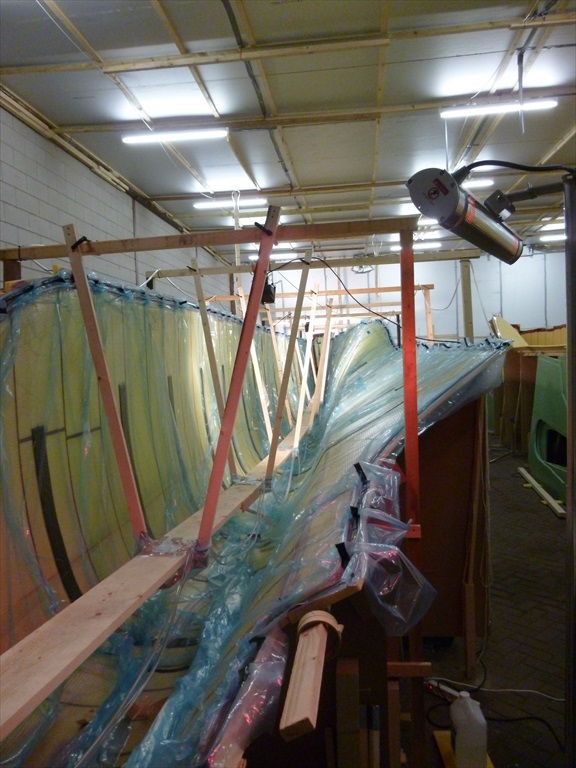
Applying fiberglass and infusion materials
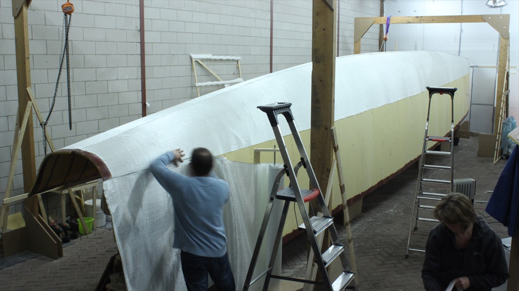
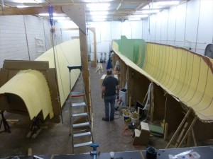
After we were sure the hull was airtight, we started wrapping the hull in fiberglass.
We started with the thickest mats (850 and 800 grams) and finished with the thinner mats (600 and 400 grams) which have a finer structure and are applied at the outside. We were satisfied with our 1 mm milling band as it provides good reference to where to place the mats. We tailored and stitched the first mats on the keel (overlapping at least 5 cm).
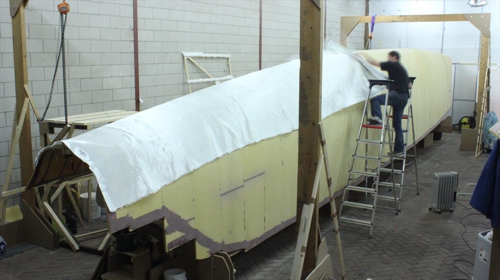
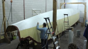
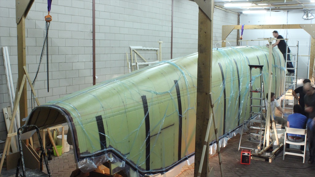
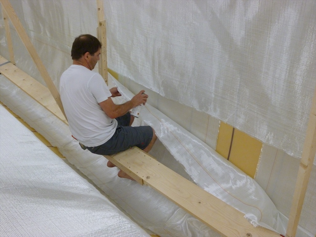
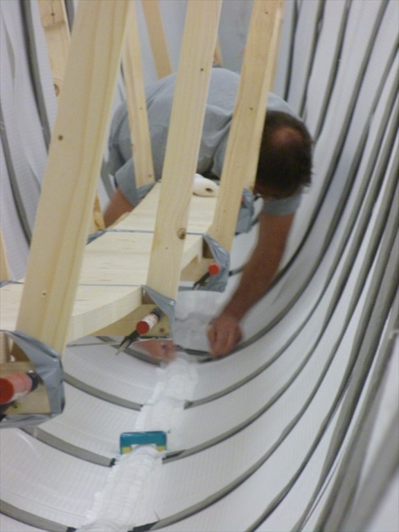
Once again, we needed both hands and feet to apply the layer above the water line (see below), motivating us to create a smart tool. A small transport “vehicle” including a pipe and a few bars was all we needed to get the job done.
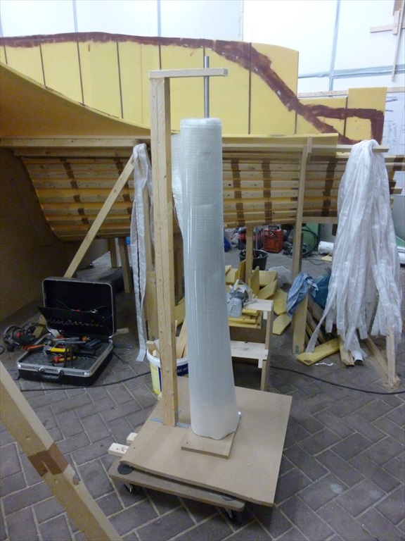
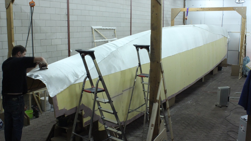
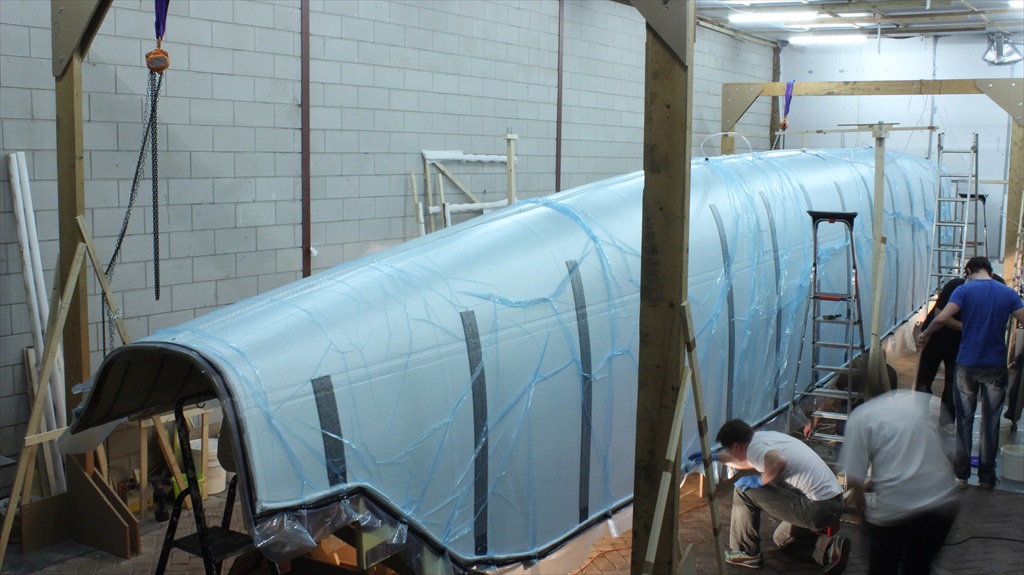
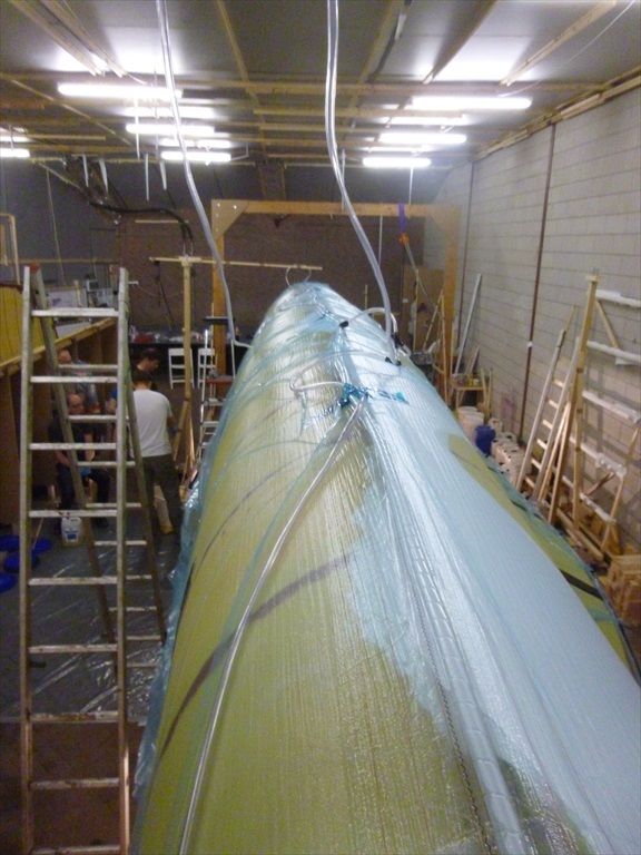
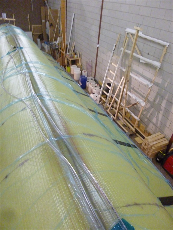
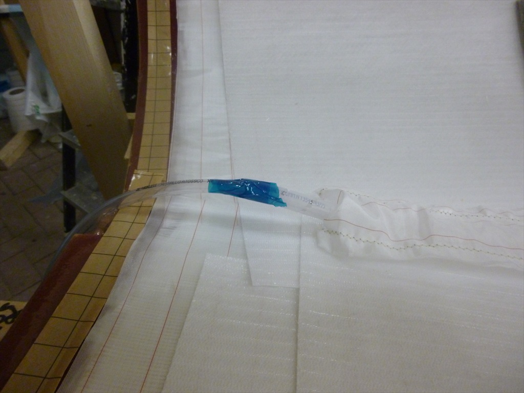
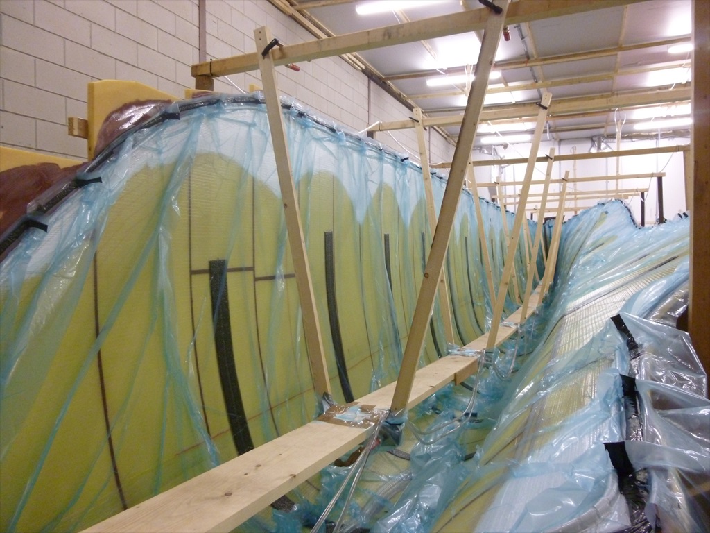
Whilst Porter was applying the fiberglass and complex Lora prepared the vacuum lines. A thick spiral hose (14/17 mm) wrapped in peelply along the bottom is used as main inlet hose. All Enka hoses are again vertically applied with 1-meter interspace. Two thick spiral hoses on top of the keel are used as (drain) hose. And again, we cut the Enka hoses on the backside to ensure a steady drain of epoxy.
Well, then there are always the easy and hard bits to stitch.
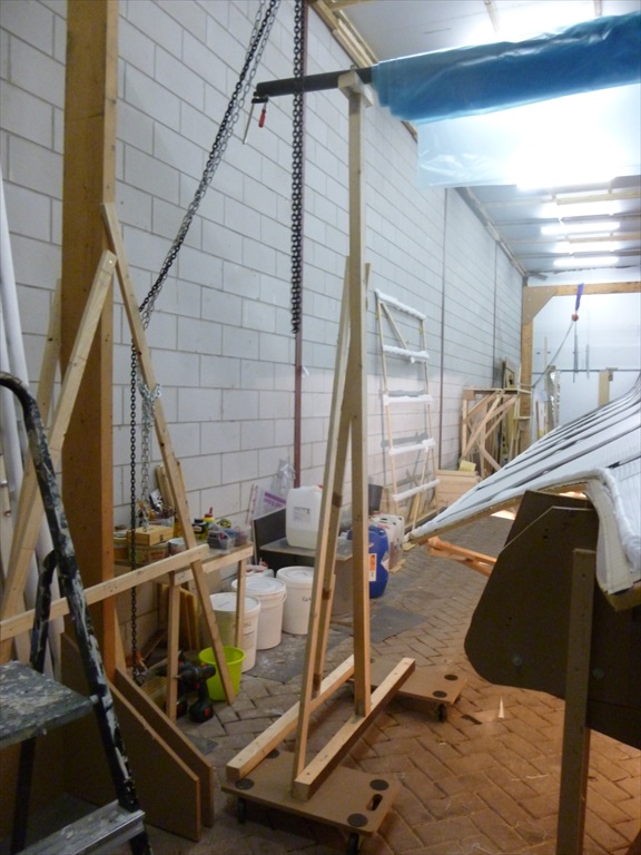
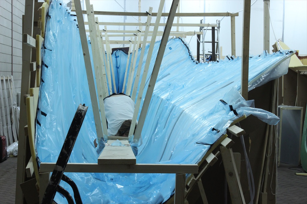
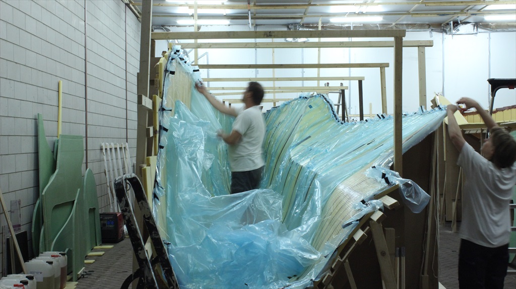
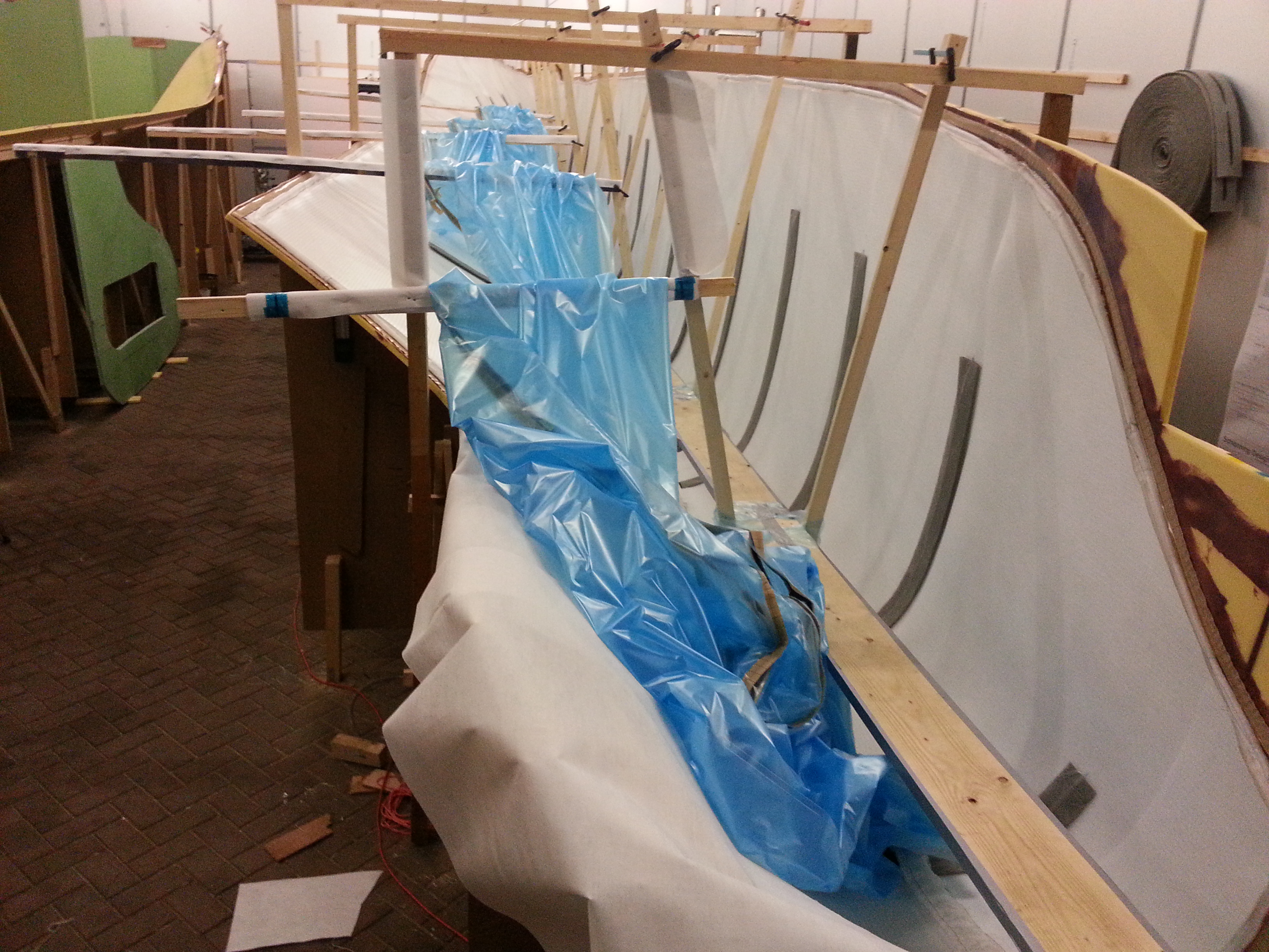
We needed a few thoughts to determine how we were going to unroll the vacuum bag (6 mtr / 20 mtr) as easy as possible without forming small holes or shifting the infusion materials.
Eventually we created two mobile frames holding the vacuum bag, so we were able to gently unroll and apply the bag from the front to the back.
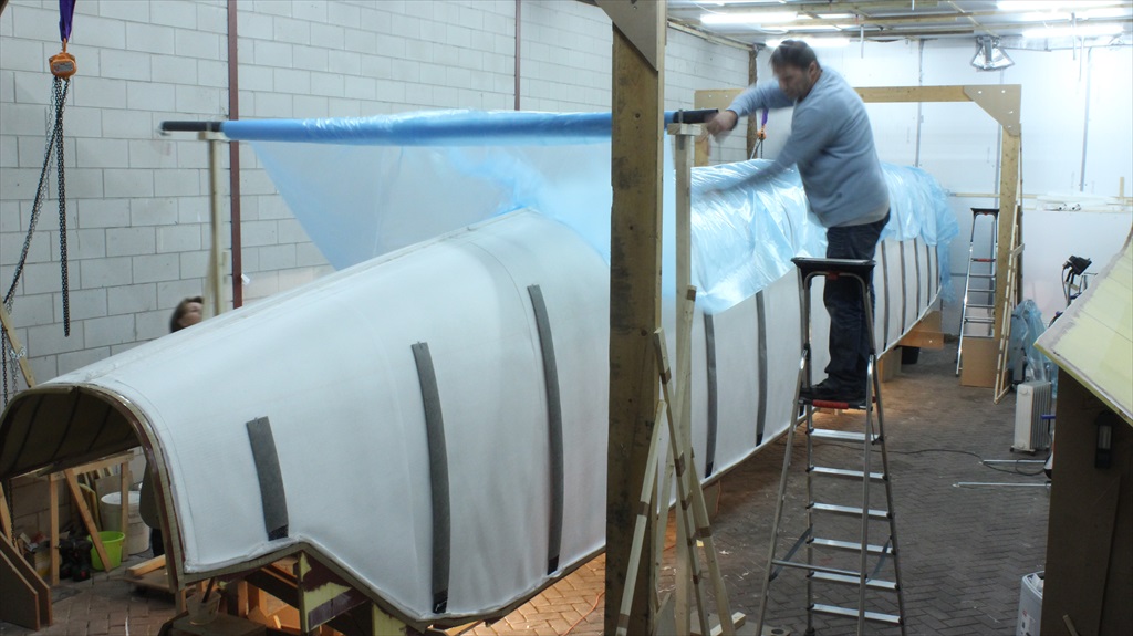
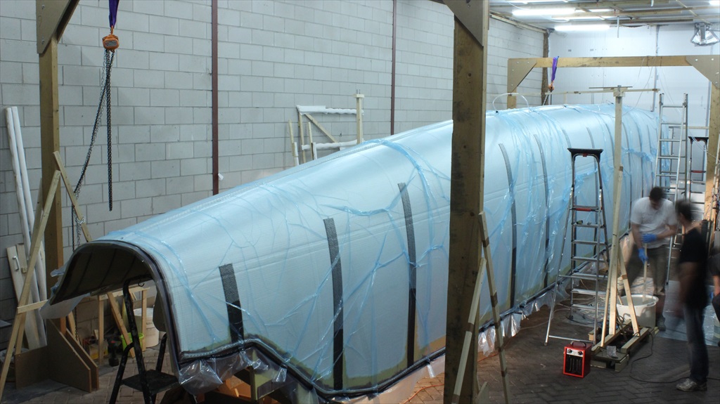
Applying the vacuum bag on the outside of the hull is much easier than on the inside, as the vacuum bag is now hanging over the hull and doesn’t stick to the edges. Not having to balance on our homemade gangway is also an advantage.
The tacky tape is now only applied around the hull and to all spots where creases are made in the vacuum bag, opposite to the inside of the hull where the tacky tape was applied around the entire vacuum bag.
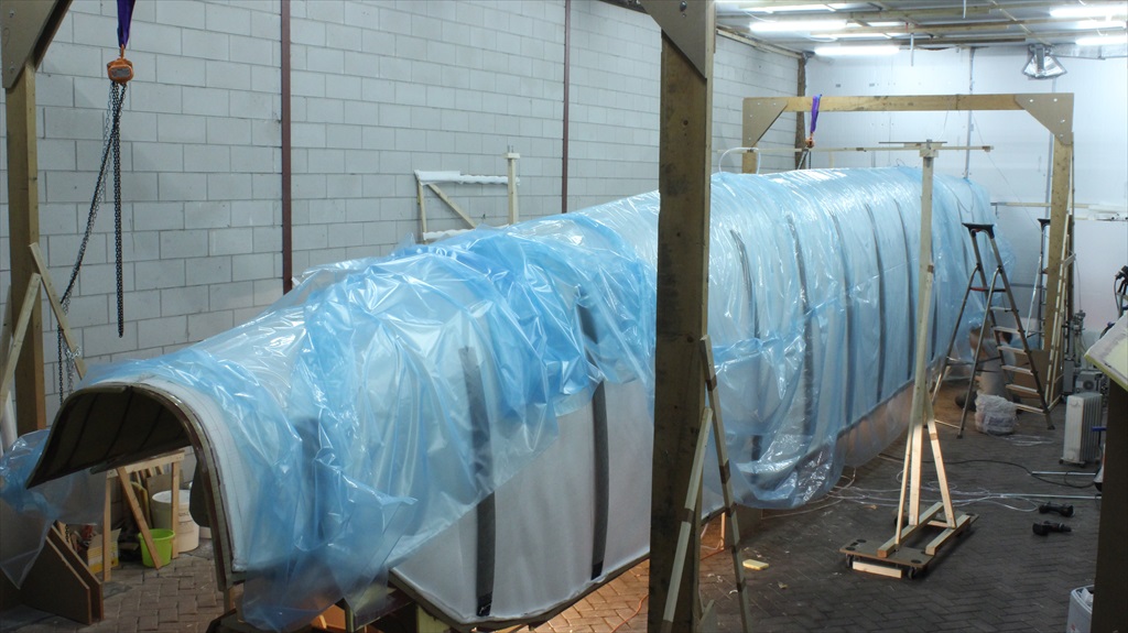
Vacuum test
Still, it remains a precise job. When you have to tape nearly 30 meters including all necessary creases, a small mistake is no surprise.
By starting the vacuum pumps it was time for the first vacuum test, to see if everything is airtight. As soon as all air is out and everything is 100% vacuum, we closed the valves on the vacuum pumps. If all is well, the vacuum % should not change. Unfortunately, after 10 minutes the vacuum % slowly reduced.
Together with the air leak tester we followed the main tape edges and found two small holes we sealed. We found a small part of a seam on the inside without fiberglass, but fortunately we were able to seal the entire hull.
At the same time our regular side kicks, Pepijn and Joris, during these larger projects arrived. Additionally, Roland and Rudi showed up to help as well.
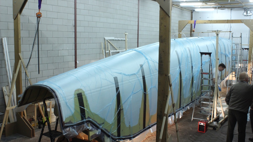
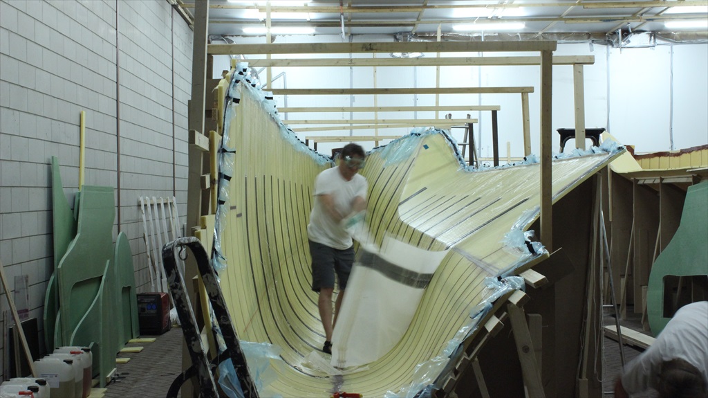
The vacuum infusion
The first batches of epoxy are mixed and the inlet hoses are secured to the bucket of epoxy. All four inlet hoses (two on each side) are still closed with clamps, resulting in small air bubbles between to opening of the hose and the clamps. One by one we filled all four hoses until approximately 5 cm below the hull (by opening / closing the clamps). In this way, all air is suctioned from each hose and will all four hoses start at the same level.
By opening all four clamps, the infusion project starts.
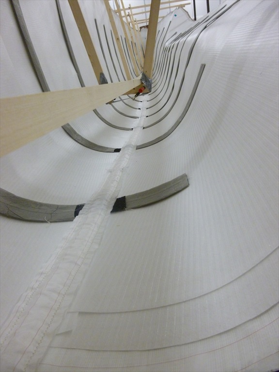
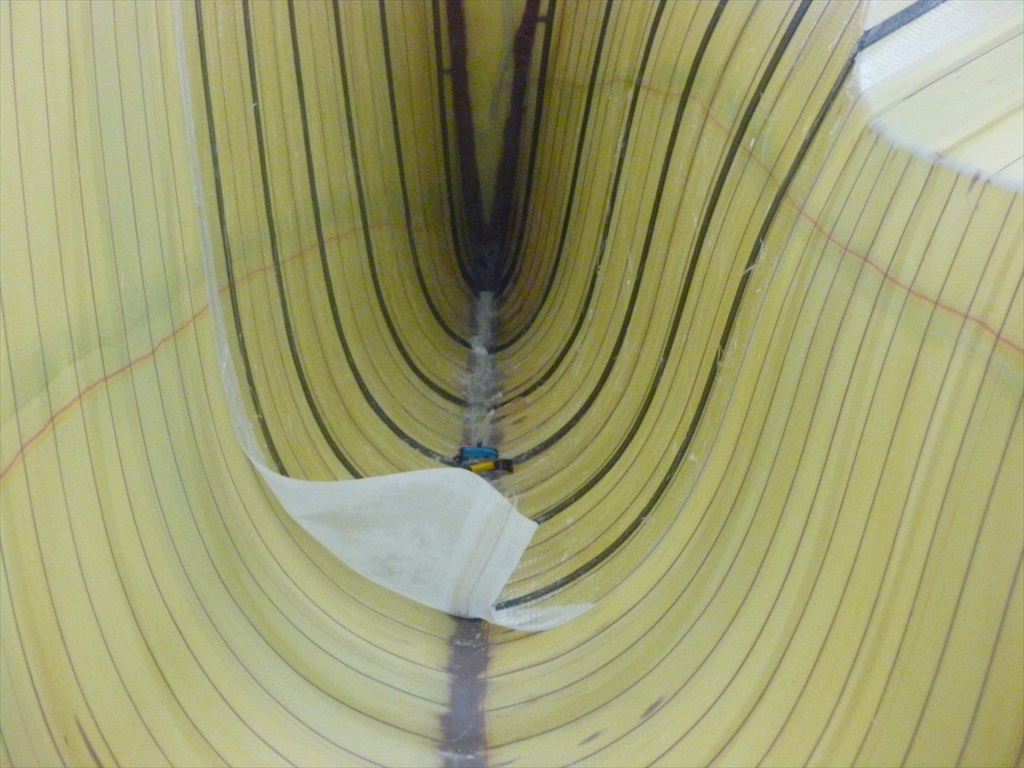
The lower inlet hose fills first and spreads the epoxy through the compoflex (white) and the vertical enka hoses (grey). Due to the rough core of the enka hose there is less resistance, which lets the epoxy run faster through the hose. In this way, the epoxy runs to the top from three different directions. The light grey enka hose turns more dark when epoxy flows through, where the white compoflex hose turns transparent and shows the yellow foam when epoxy runs through.
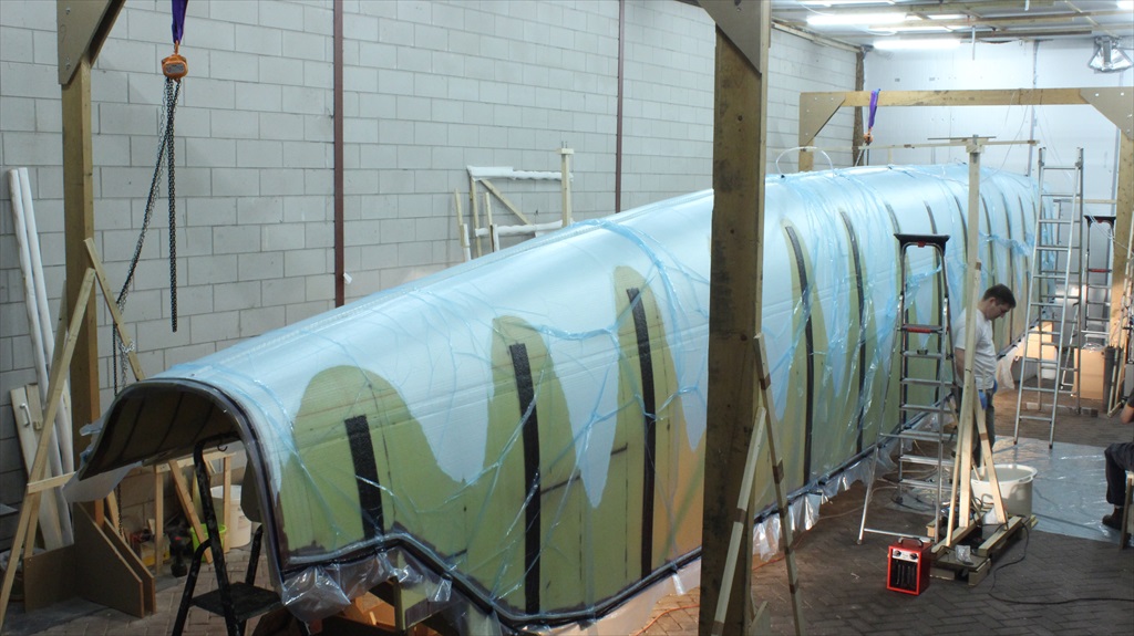
The other side of the hull is also making good progress.
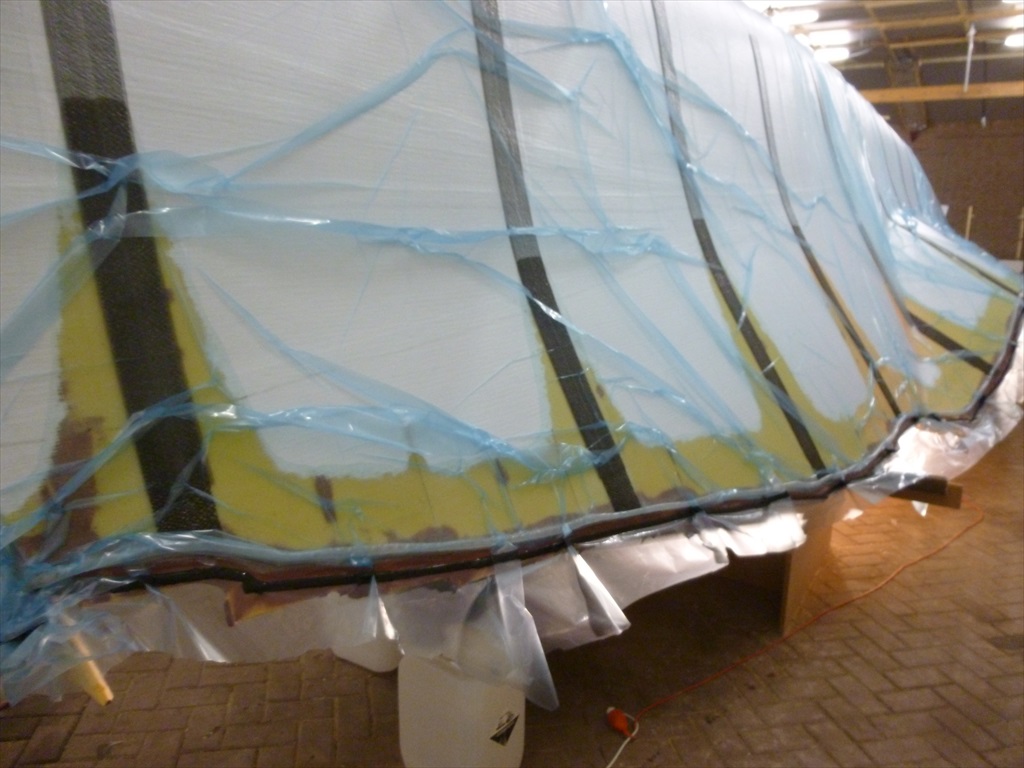
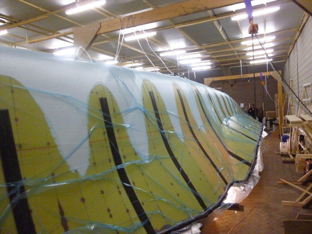
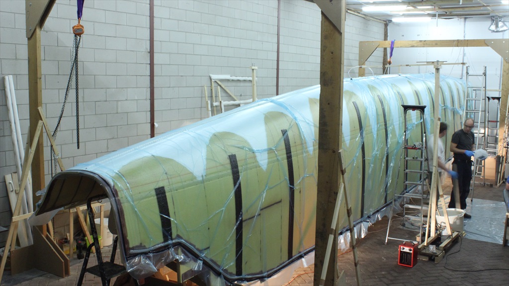
The so-called “runners” are now clearly visible and are stopped by the micro balloons we created before. These micro balloons make sure that the epoxy only continues whenever the entire surface is at the same level.
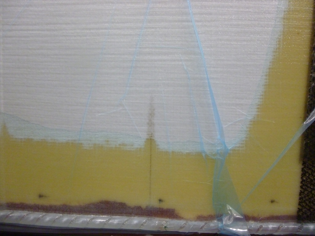
At first, it looks like one side reaches the vacuum hose before the other, but when you look closer at the end of the project you can see it levels.
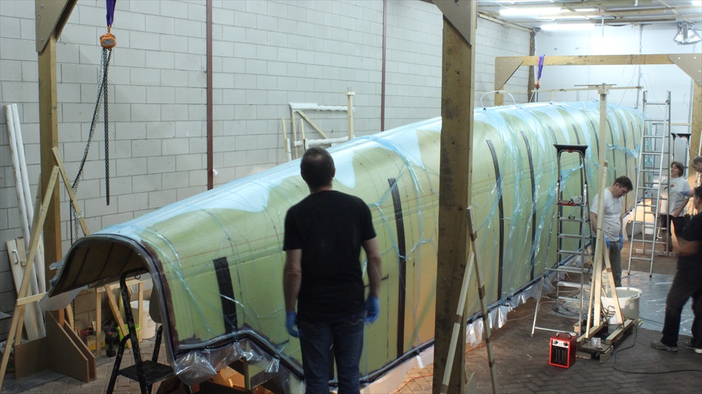
The final stages of the infusion always take longer, as the resistance between the inlet and vacuum hose turns bigger. Look closely, and you’ll see the team relax.
Altogether it took little over 2 hours to laminate the entire 65m2. Around 14:00 only Lora and Porter were left in the shed and started looking for the first signs of success. At 19:00 the epoxy was transforming into gel and we were confident enough to go home and get something to eat. Of course, we went back for two small checks at 23:00 and 02:00, and eventually switched off the pumps at 09:00 (indeed, we set the alarm).
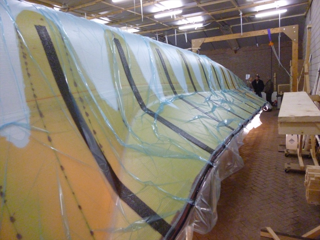
The vacuum infusion result
The next three days, we spent outside the shed and gave our hull some time to harden (we needed some time as well).
Viewing the final result with our own eyes eventually gave us some rest. Although it’s hard to get this feeling on photo, we are still very proud with the result.
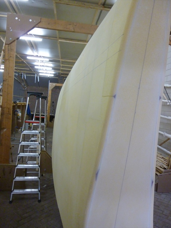
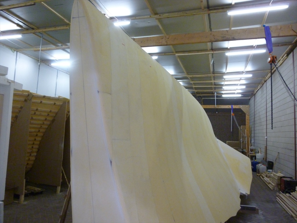
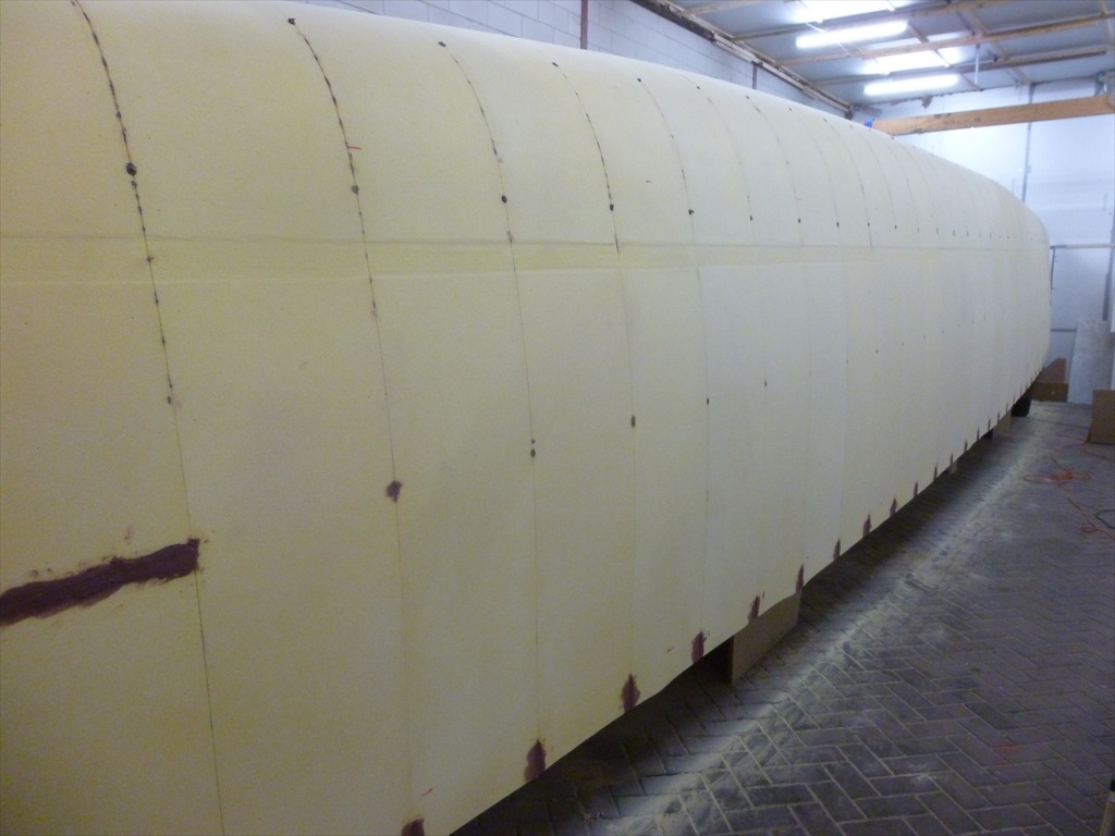
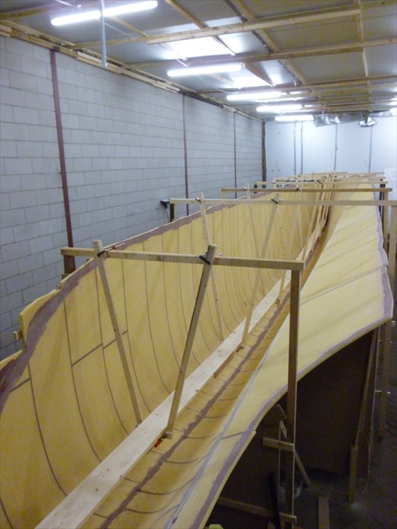
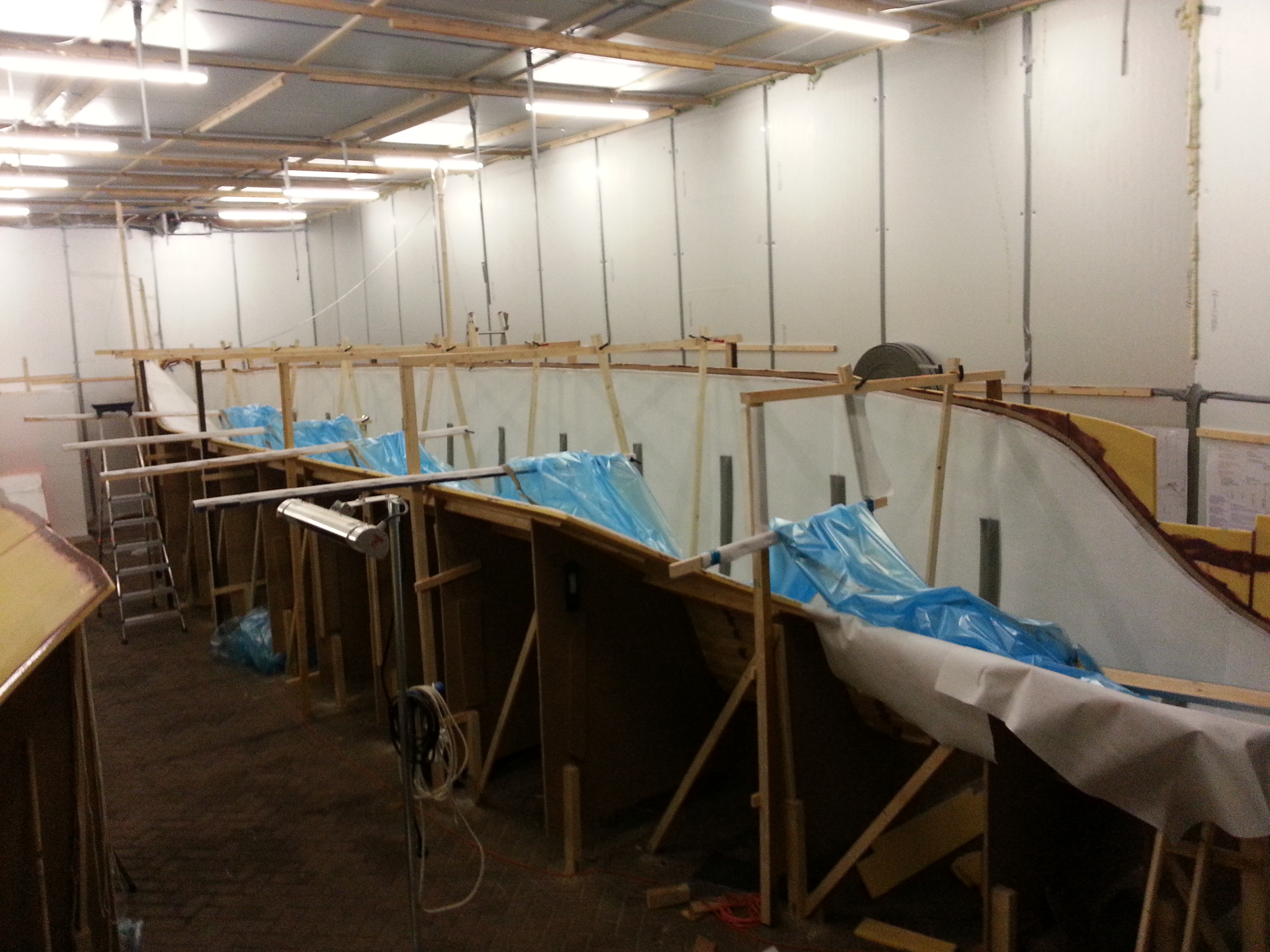
Vacuum infusion of the outside of the 51ft (15,5 mtr) hull
On to the next stage: sanding and filling.
The post Vacuum infusion hull out side appeared first on Bouw project G-Force1500C catamaran.
]]>The post Turn the hull appeared first on Bouw project G-Force1500C catamaran.
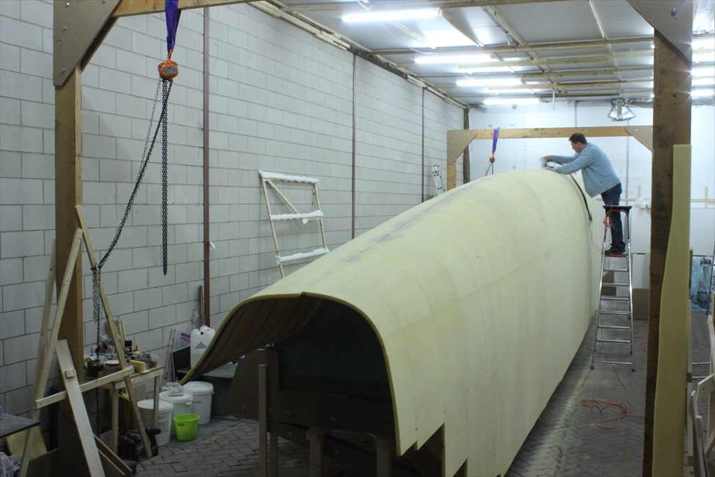
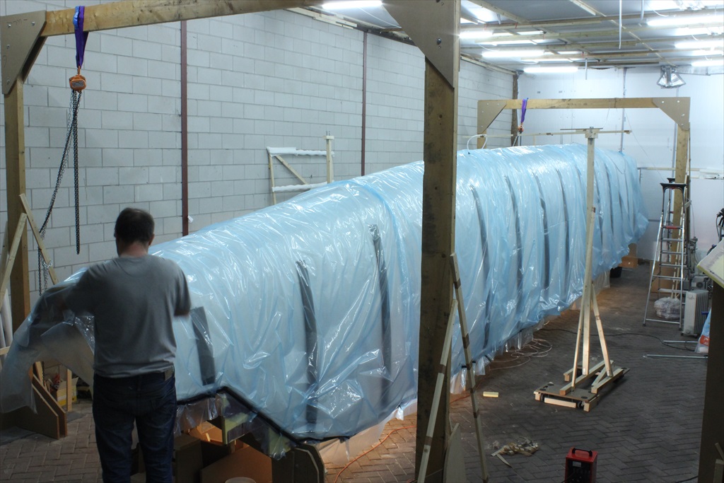
]]>Breakdown the mold
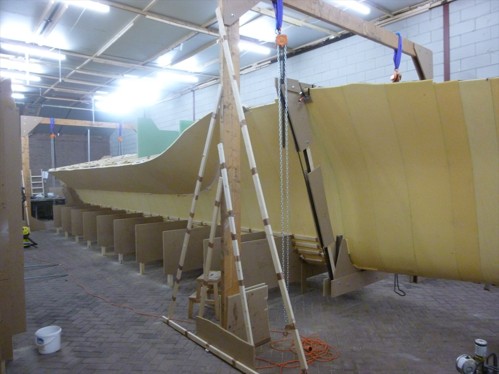
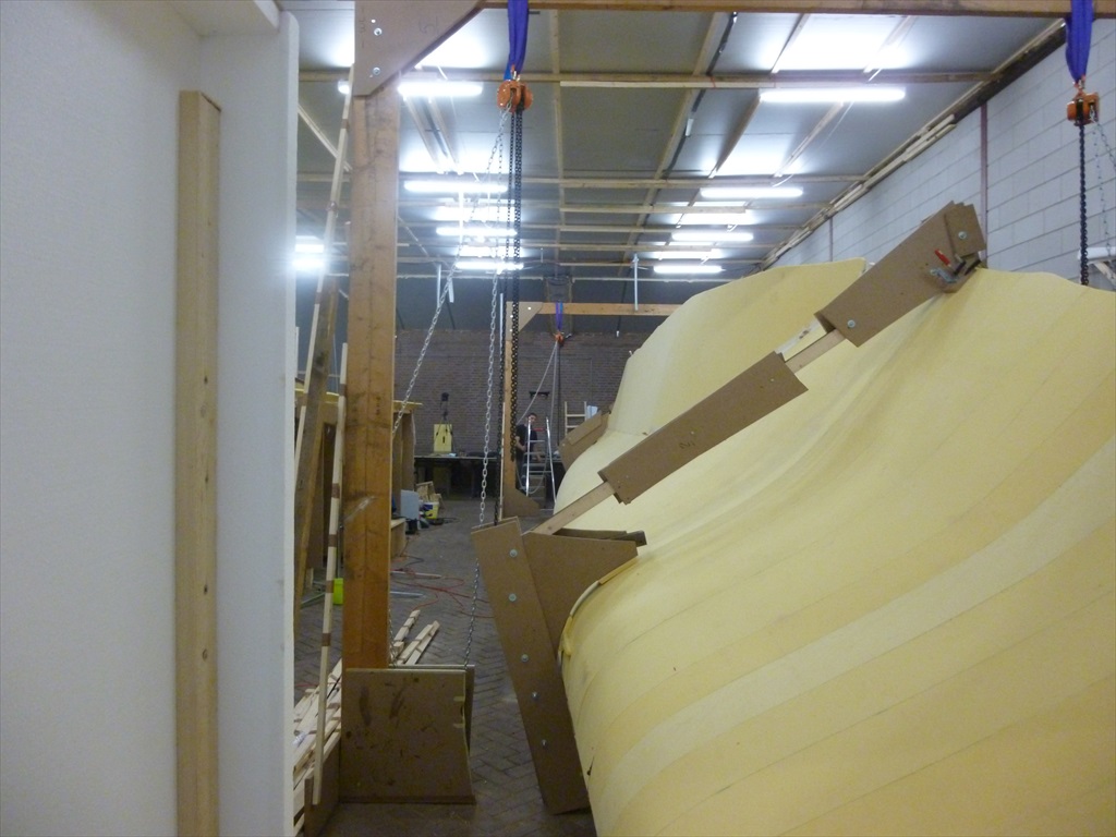
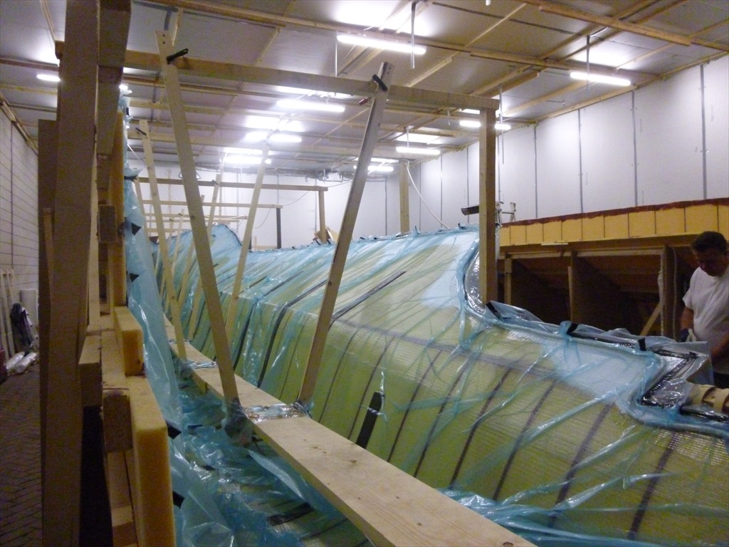
The time has arrived to break down the support beams and turn the hull. Exciting because the hull only really gets his sturdiness when the glassfiber mats are attached on the outside. The trusses in the hull ensure some extra sturdiness and therefore enabling us to turn the hull. The first step is to decide which part of the support to break down first, an important factor is the local sturdiness in the hull.
Having the support structure in parts, showed to be a real convenience. The thousands screws in the support structure are being removed. They come out much easier then they went in 8 months ago. Alertness is required to ensure we do not forget and leave screws in the hull. After some crawling we can remove the structure parts below the waterline.
Turning mold
As expected the middle of the hull needs extra sturdiness. Now that we don’t enter the hull as often as before we are able to place the final bulkheads in the hull. On the bow and the stern we place 2 molds on which we lift and turn the hull.
A few support beams, some leftover MDF and Corecell and a few bolts and a few more just in case. You cannot secure it enough. The leftover Corecell protect the hull from any scratches, this worked well by the way!

Hoisting frame
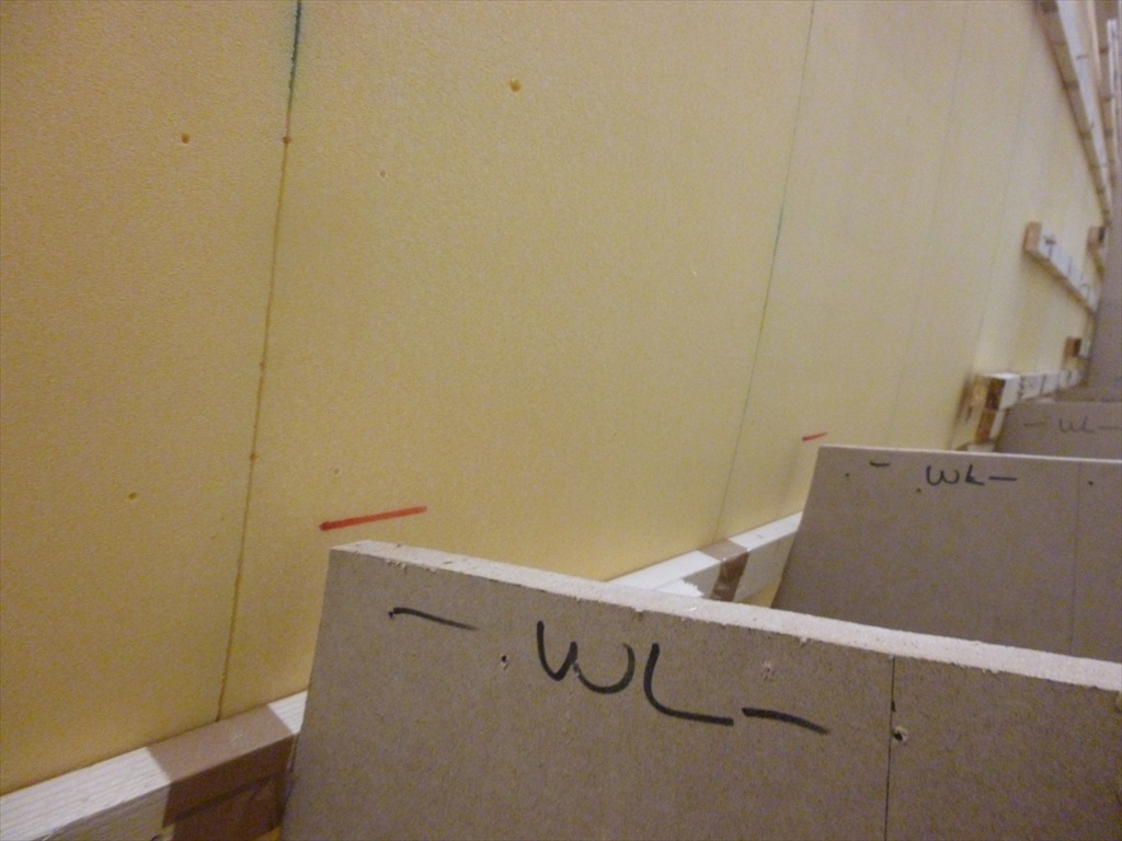
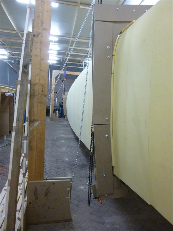
Now that we have a basis we made a huge support structure above the hull on which we connect the chain cable. This way we keep control of the hull before we remove the rest of the support beams. This moment was also ideal to draw the waterline on the hull.
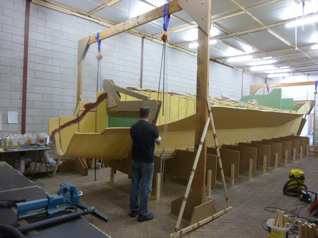
Ready to turn the hull
One support beam away from being completely of the floor. The turning can almost commence. The turning itself went very easy. Porter stood by the stern and Lora at the bow. Lift the side of the chamfer (the angled side) as far as possible and lower the other side. In 5 strokes we had rotated the hull 180 degrees.
With a laser pointer on the trusses we ensured and watched if the process went parallel.
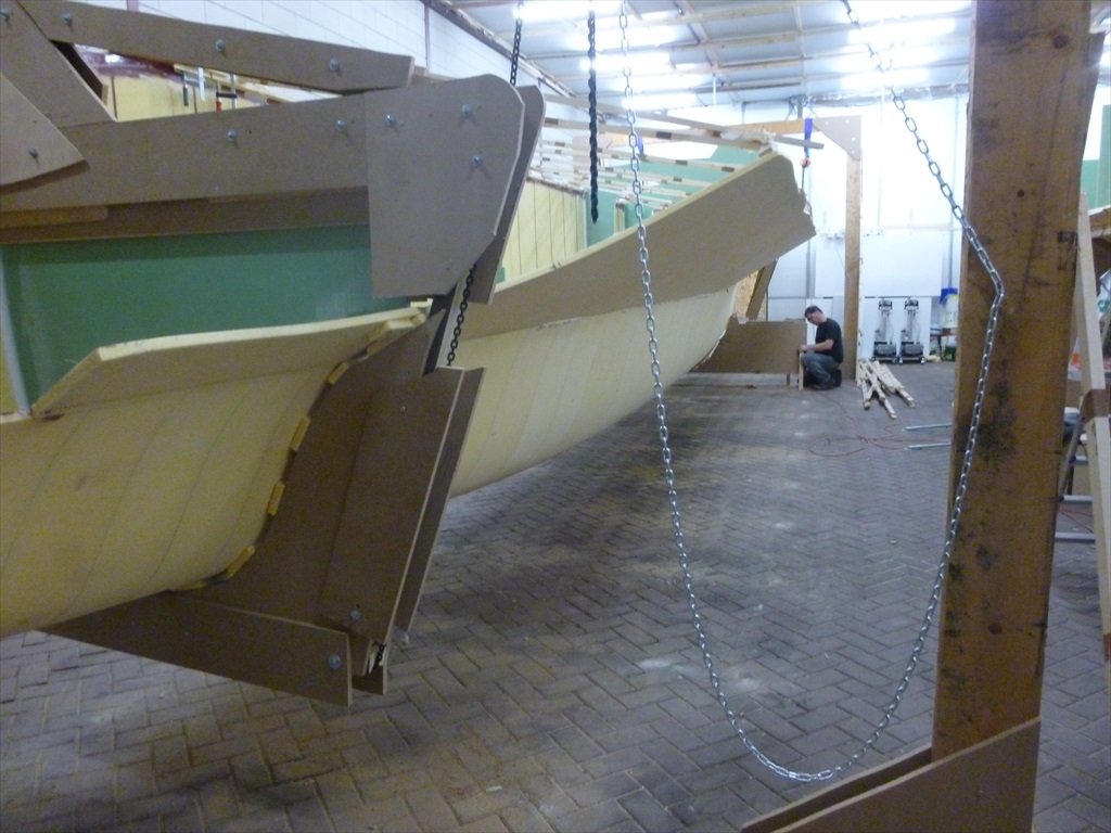
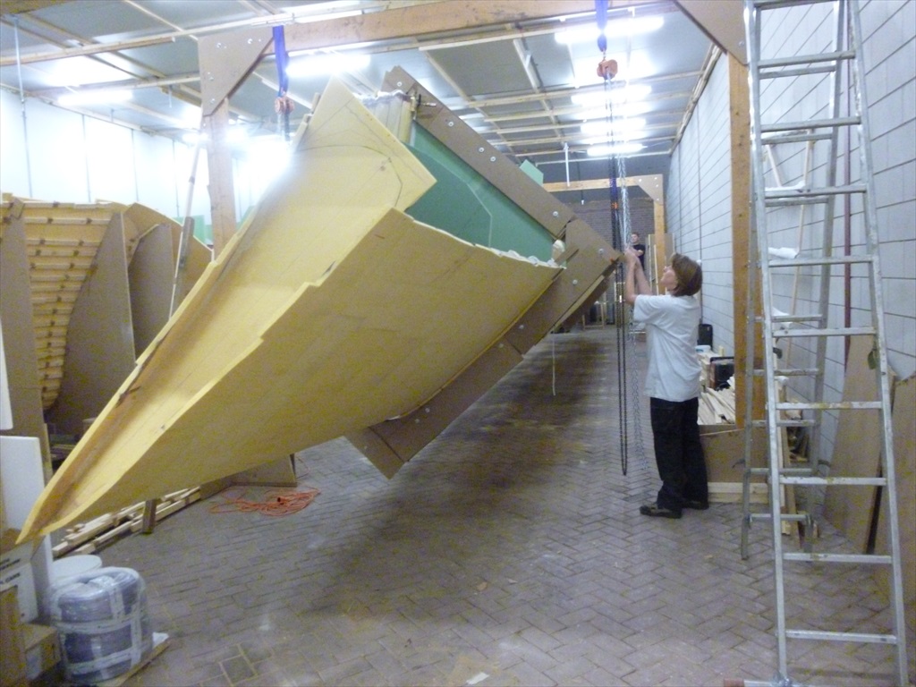


We released the rotation molds and in a couple months we will mount them again to rotate the hull. The next couple of months we will be occupied with laminating the outside hull. For now another milestone has been reached!
In the clip below you will see how smooth it went to turn the hull.
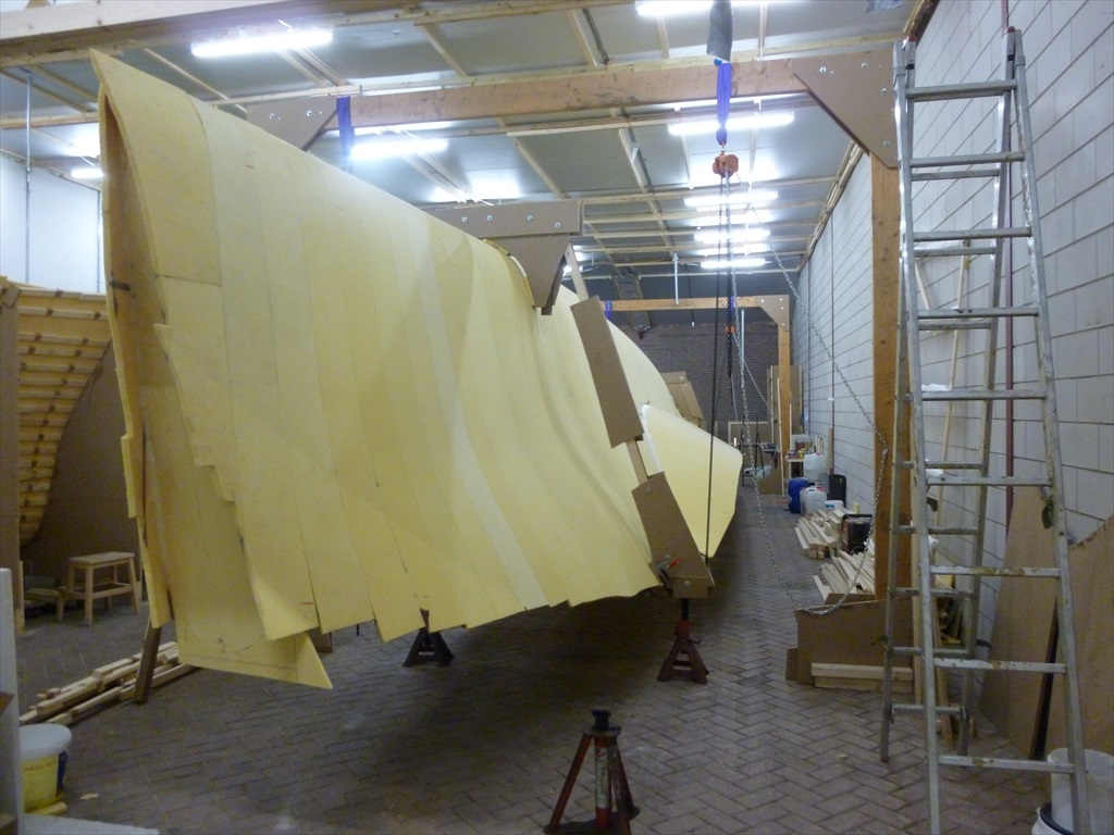
The 51ft (15,5 mtr) hull released from the mold and turned 180 degrees
The post Turn the hull appeared first on Bouw project G-Force1500C catamaran.
]]>The post Vacuum infusion inside hull appeared first on Bouw project G-Force1500C catamaran.
]]>Porter has a vivid memory of the build of his previous boat. The lamination of the hulls with the hand-lay-up method was a sticky mess. So far we are very satisfied with the choice of vacuum infusion method for the build of this boat.
After 10 or more vacuum projects on flat panels we really got the hang of it. However applying the vacuum infusion project on a 65m² surface that is 2 meters high is a sensation on a whole different level.
After deliberations with several specialist we have made the following plan of approach for the vacuum infusion on the inside of the hulls. These are the factors that we decided upon:
- All fiberglass mats are being laminated in one turn. (above the waterline 900 grams per m², below the waterline 600+400 gram per m²)+ on the positions where the ribs (doorways) are located extra reinforcement by way of an extra 600 gram per m² fiberglass mat.
- Double major supplylines on the keel with 2 extra inlet points.
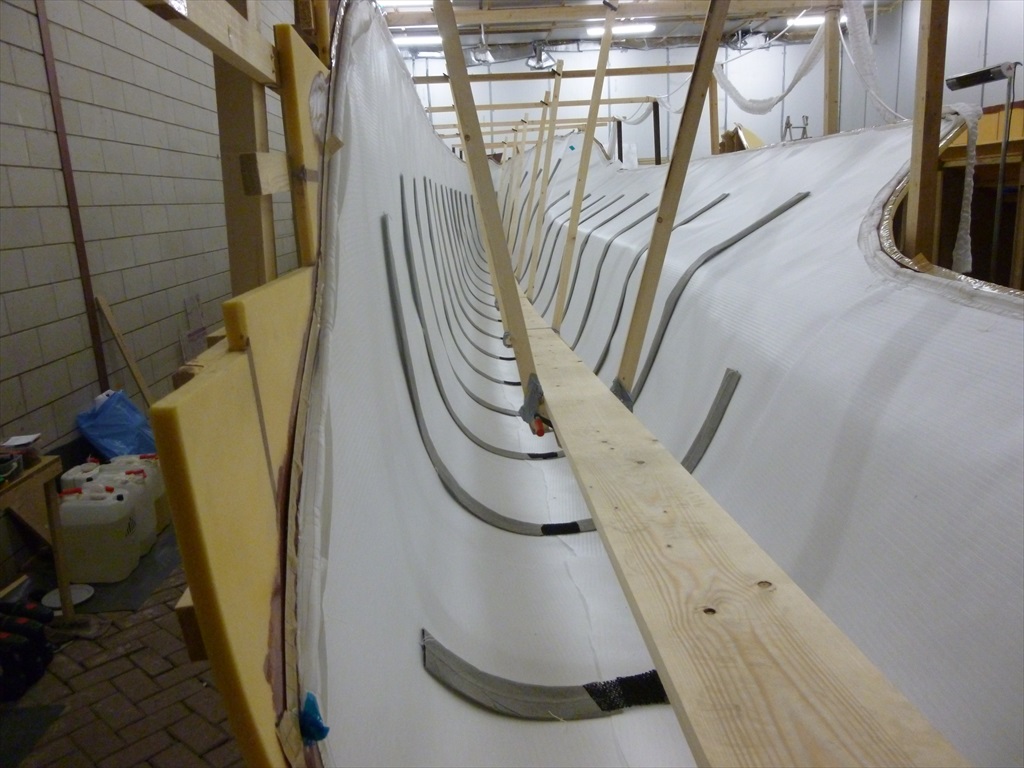
- From the keel every meter an Enka supply strip in vertical direction to enable the flow of epoxy in all directions to cover a distance of 50cm. The Enka strip does not leave any marks on the laminate.
- A vacuum hose around the topedge with 2 extra adjustable extraction points.
In closing everyone unanimously agreed: The smart thing to do is to test the vacuum first. A suggestion we agreed upon wholeheartedly.
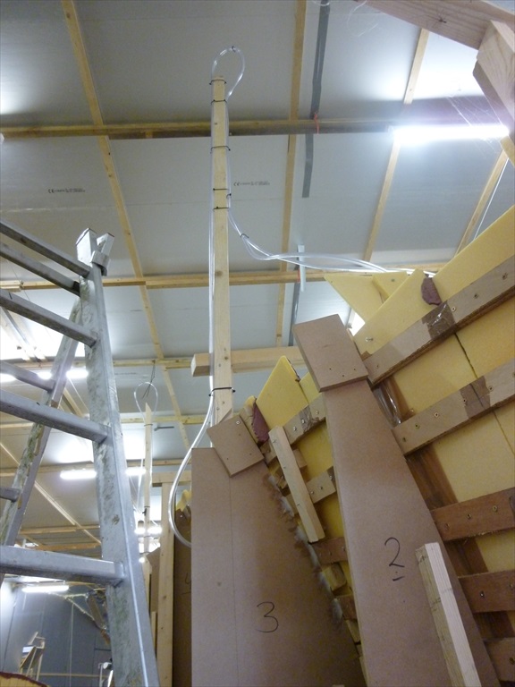
With 2 MDF plates placed in an upright position leaning against the wall we could mimic all the aspects and we saw that the chosen set up actually works.
Testing vacuum infusion in vertical way
The only uncertainty that remained was: did we succeed the packaging of the hull in the airtight vacuum bag? Did we close every seam with micro balloons?
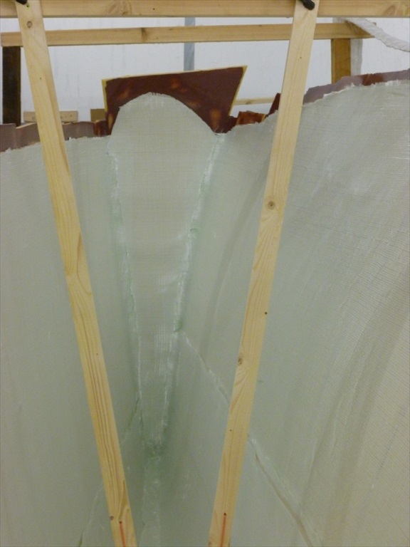
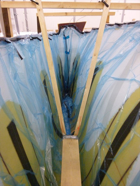
Prevention is always better than healing so before we start first a test; the most critical point in our project is the part where the chamfer passes in to the bow. Our concerns where justified as this part had allot of leaks. With our ultrason leak detector we came to the conclusion that the attachment between the hull and the chamfer needed reinforcement.
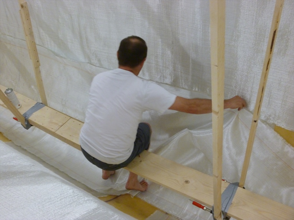
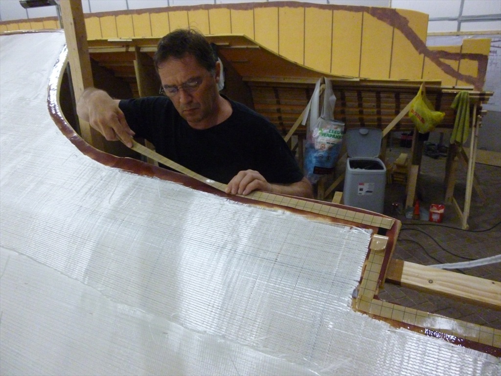
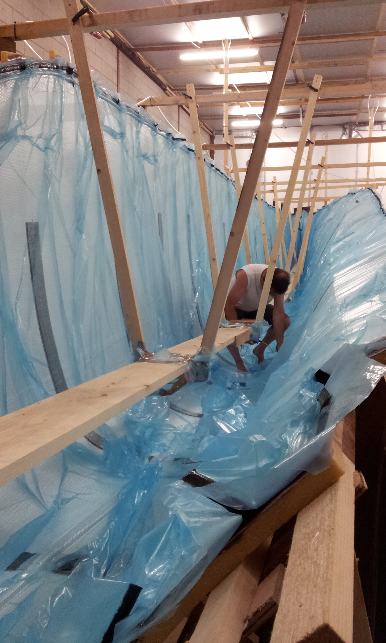
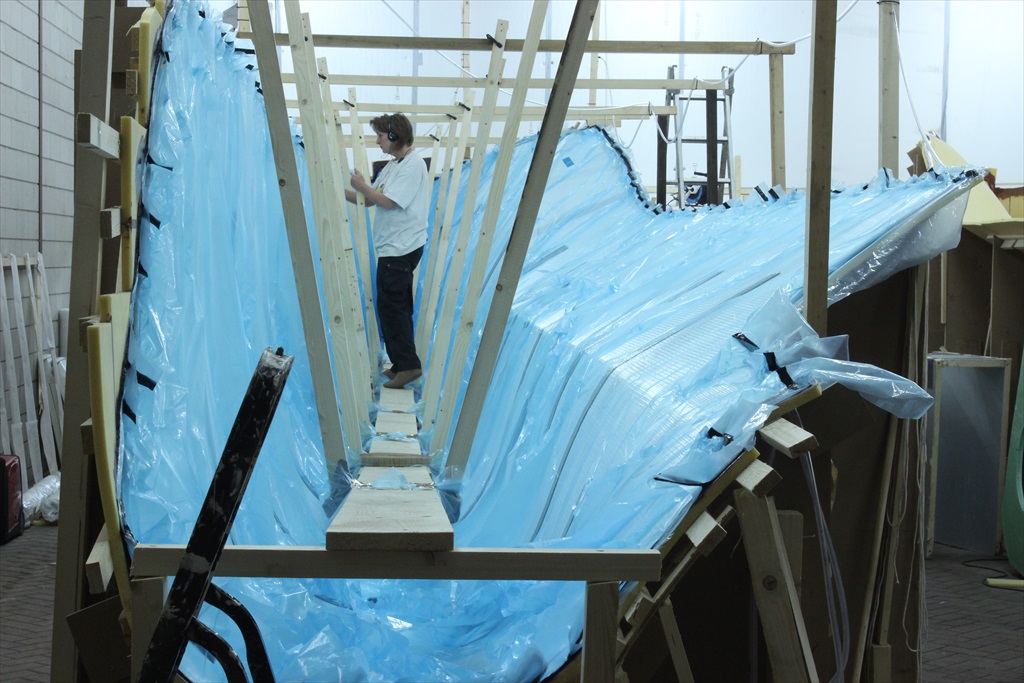
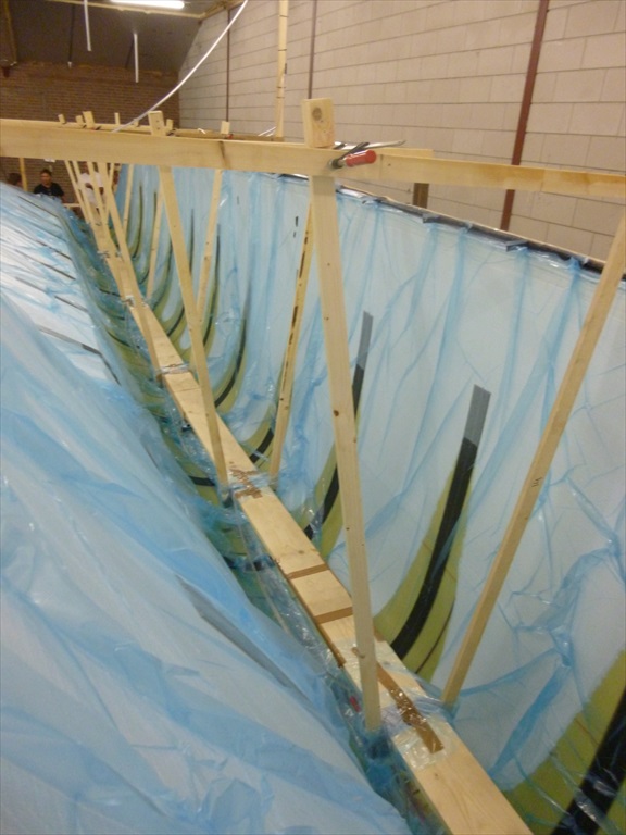
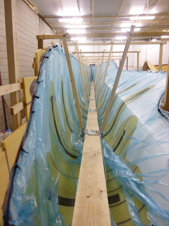
We need to add multiple layers of fiberglass mats and infusion materials. In order to reduce the risk of the materials gliding out of place, we build a walking plank in the middle of the hull.
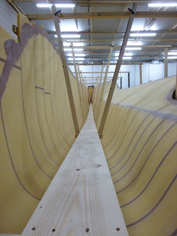
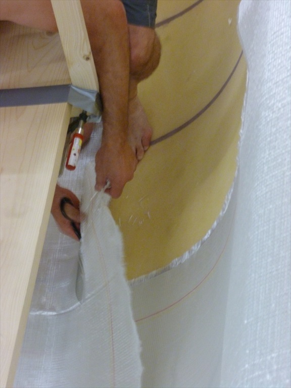
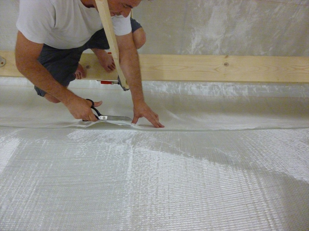
The hull is made 15cm larger then needed because then we can fix the fiberglass and the infusion material on the top part of the hull. After the hull is also wrapped on the outside of the hull we can simply cut all the extra parts off. The edge is smoothend and airtight with microballoons and epoxy coating.
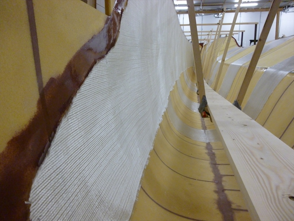
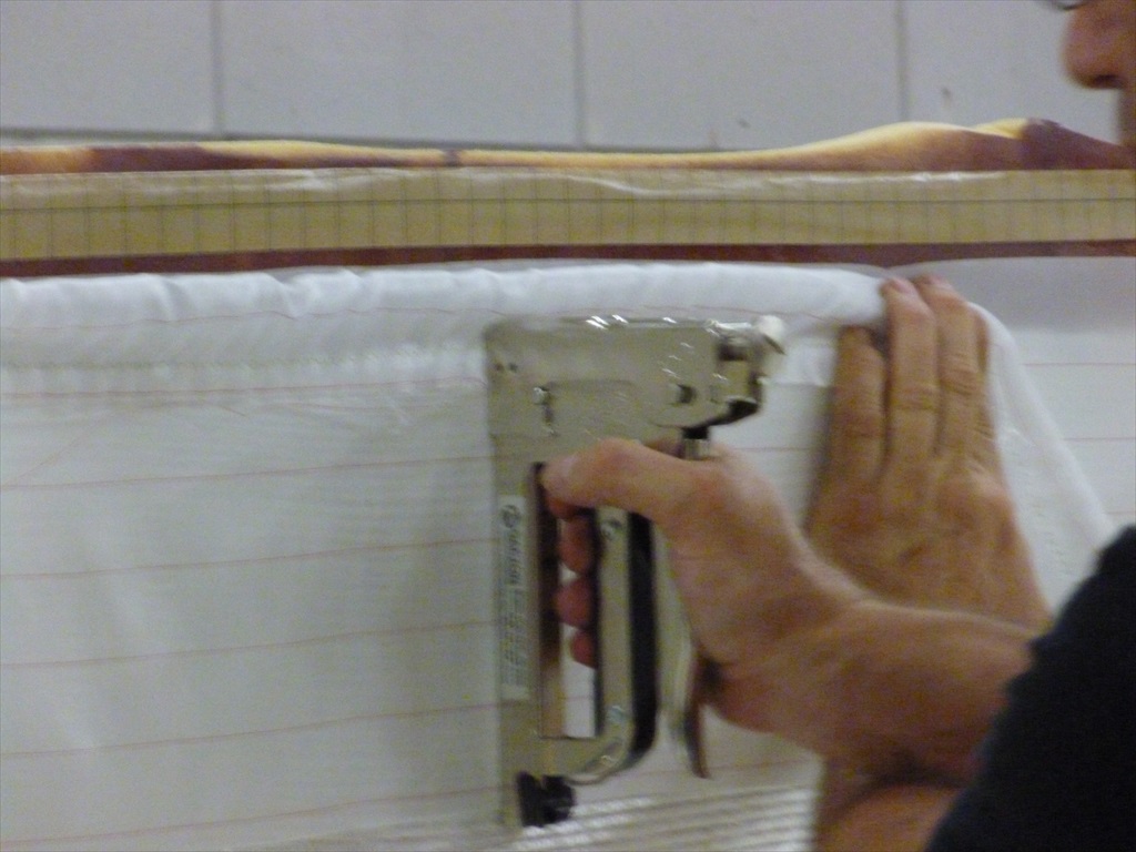
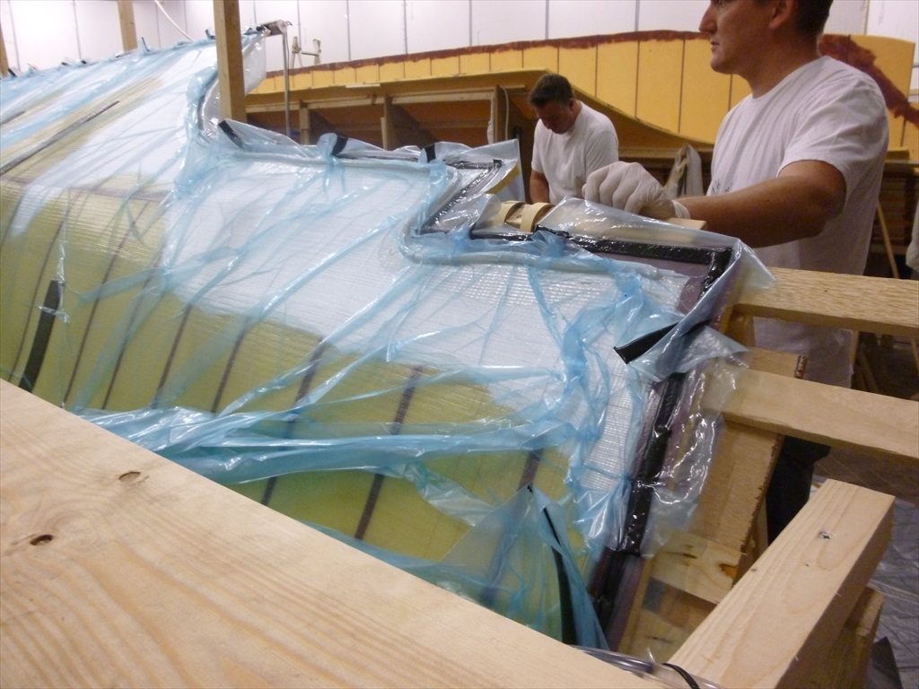
Now the wrapping can commence. First we lay the fiberglass mats at the reinforcements at the trusses, after that the mats below the waterline and we staple these with plastic staples in the topedge.
The fiberglass mats underneath the waterline have a 5cm overlap and we glue it with special squirtglue. The weight that ‘pulls’ the mats and it is really quite a hassle to form it properly.
On the keel an additional overlap of 5 cm. This way the fiberglass mats have some freedom of movement and space to expand for when the vacuum is initiated.
The small part in the bow is adjusted in size in advance. The mats of the long sides also have a 5cm overlap to ensure that no loss in strength occurs.
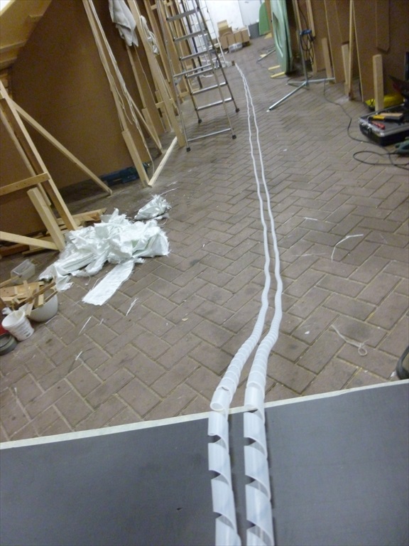
While Porter placed the fiberglass mats, Lora prepped the vacuum infusion lines. For the main supplylines we used 2 thicker (14/17mm) spiral hoses. For the vacuum lines on the topedge we used a narrower 9/12mm hose.
By stretching the hoses first a couple of times the epoxy will flow more easily. Also now we wrap the supply lines in peelply. This ensure that the epoxy will flow easier and more evenly. In the supply line will have some residue epoxy that will now be trapped between the lines and the peelply instead of on the hull. This makes removing the supply lines and peelply much easier when the epoxy is hardend.
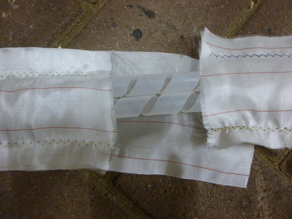
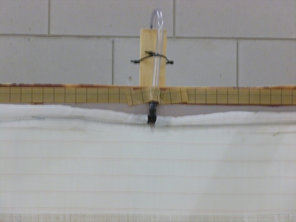
First we stick the tacky tape to the edge. The vacuumbag will be attached to the tacky tape in the end. The tacky tapis a good reference for the rest of the vacuum materials. The wrapped vacuum hose is stapled as high on the edge as possible. On several points we connect a closed supply drain that we can manage with taps.
Similar to the flat panel infusion projects we use the all-in-one Compoflex fibers serving three main purposes. First, as a flow mat which equally distributes the epoxy. Second, a release film ensuring the vacuum bag does not stick. Finally, as peelply ensuring the Compoflex is much more easy to detach without damaging the laminated fibreglass.
By applying the compoflex a few centimeters below the vacuum line, the epoxy runs slowly at the end ensuring a more equal distribution in the extraction line. The small edge of peelply underneath prevents the vacuum bag from sticking to the fibreglass.
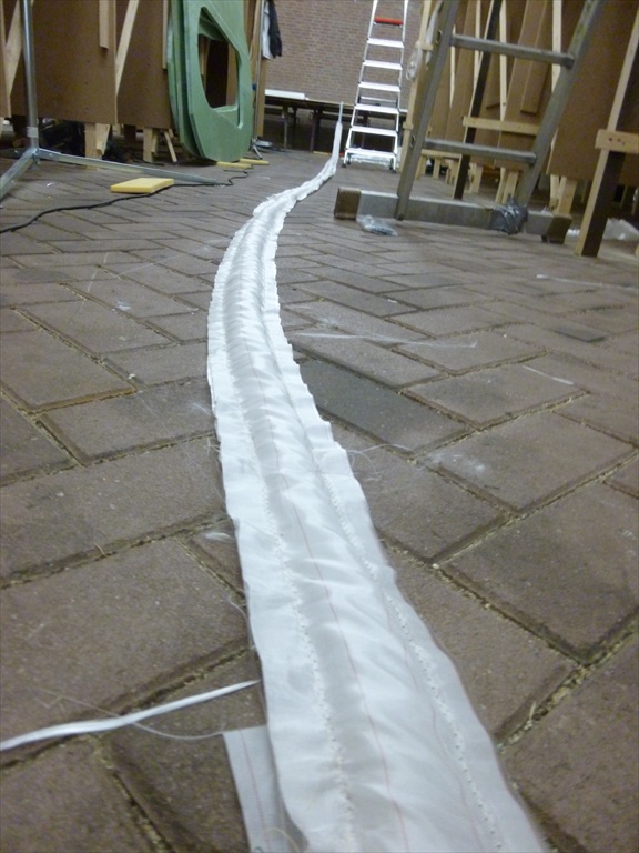
We use the Enka lines to create a sort of fishbone to spread the epoxy on the large surfaces. Spiral lines might leave a print on the laminate; therefore we used the Enka lines.
We spread the Enka lines with approximately one-meter interspace and approximately 50 centimeters below the vacuum hose.
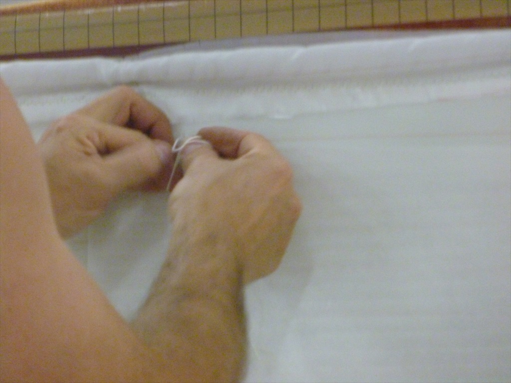
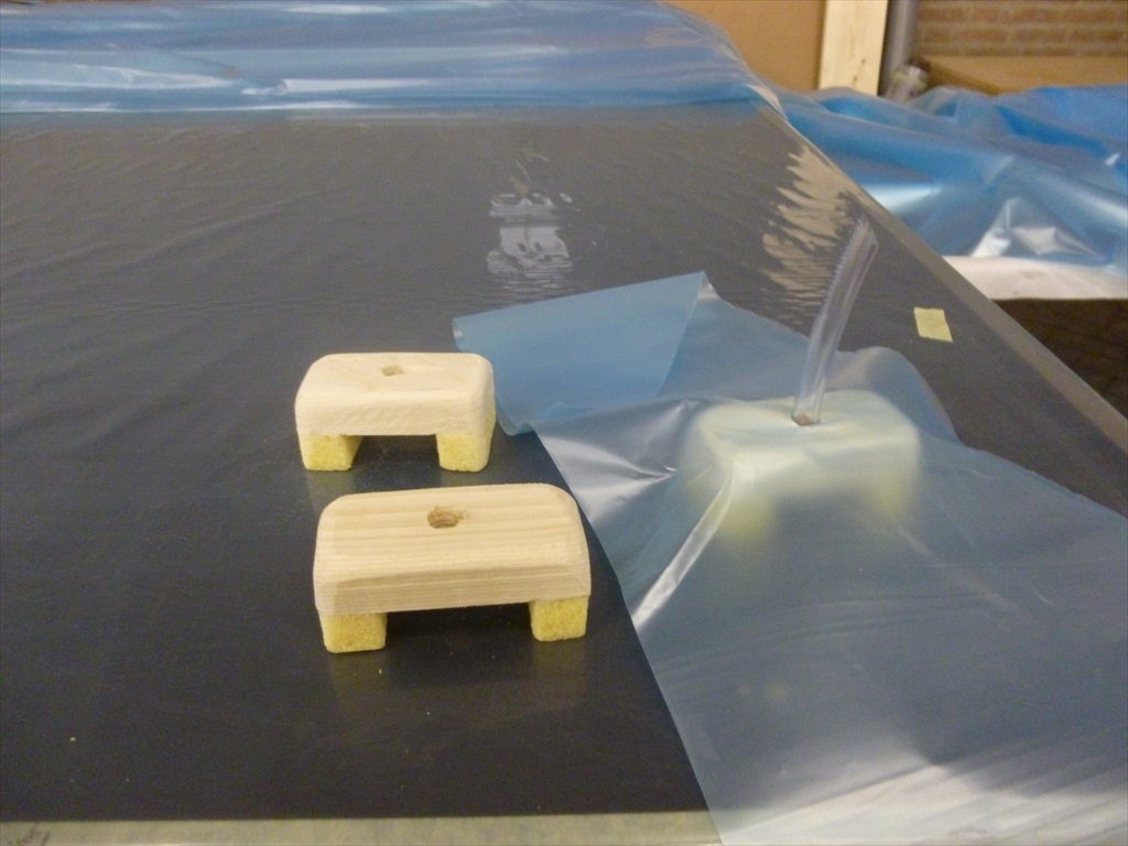
The wrapped inlet hose is on top of the keel across the opened Enka line. We created 3 inlet points. To prevent the inlet hose from shifting, we used wooden blocks and CoreCell to place over the inlet hose. Additionally, we attached the inlet hose to the compoflex with a small wire on different places.
The first inlet point is at the back of the ship. The epoxy should flow through the spiral hose towards the Enka lines and through the compoflex until everything is filled with epoxy.
The main extraction point is on top of the highest edge. As soon as the entire hull is filled with epoxy, the extraction line will fill the bucket. By placing the line upwards (more than one meter) there is eventually less epoxy in these buckets.
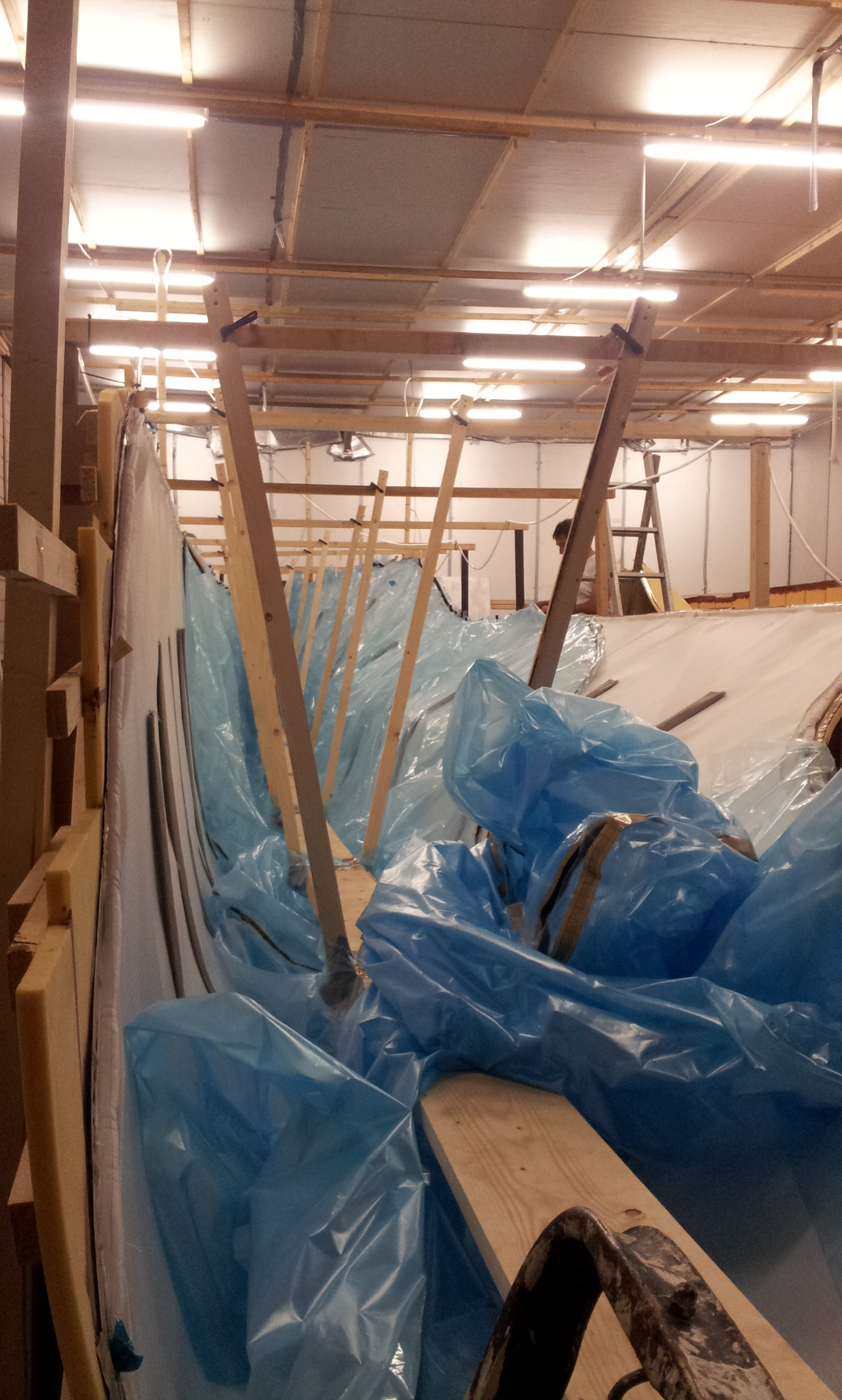
Applying tacky tape at the edge of the vacuum bag eases the application of the vacuum bag. We needed to wrap up the vacuum bag to place it inside the hull without damaging it or shifting the lines.
It was quite a struggle, but after taping the first bits it became more easy to tape the rest. We should really rethink our strategy for the second hull. Every 34-45 centimeters we create creases to ensure sufficient space for the bag to shape itself once the vacuum pumps are running.
Time to test our set-up.
Although we set up two pumps, only one is actually doing the job and the other serves as a back up. We use two sets of tanks to absorb the remaining epoxy. Per set we start with only one tank and change to the second once the absorbed epoxy begins to react. There is enough time to empty the first and use it as back up again.
The moment is there… will it be airtight?
As soon as all air is suctioned from the vacuum bag, we close the pump valves to check whether the vacuum % remains the same. Unfortunately, the percentage slowly drops meaning there is at least one leak.
After a few hours checking with the leak detector we found several seams in the edge of the bag and the bag itself. One small leakage was located in the excess edge of the hull and was easy to repair.
Eventually we fired up the vacuum pumps and had a minor decrease of the vacuum percentage, but within our margins. So, the moment is there, start the infusion!
With a couple of extra hands of our good friends we started dividing tasks. Pepijn took care of the main inlet tank. John and Joris regularly mixed new batches of epoxy. In this way Porter and Lora had no specific task and were able to monitor everything and assist the others when necessary.
Eventually this “exciting” moment of our project turned out to be another relaxed day. Within just two hours the entire hull was filled with epoxy.
Just after, we especially had to check the outlet tanks and empty them on time. We used light bulbs to keep a steady temperature of 23-25 degrees Celsius to enhance to gelling process of the epoxy. After six hours de first signs of “gelling” appeared and we turned home after eight hours.
Check the movie below, you’ll see how the epoxy steadily flows into the hull.
Vacuum infusion of the inside of a 51ft (15,5 mtr) hull
This Photo album shows more pictures about the vacuum infusion project of the hull. Open the first picture to read the text and scroll through all pictures.
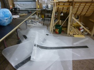
After two days of hardening we were extremely curious for the final result. The vacuum bag was easy to remove and by bagging the entire bag we were again shocked by the size of it.
We started with disconnecting the inlet hose on the keel, after that the Compoflex with the attached Enka hose was easy to remove. They were easy to transport once folded.
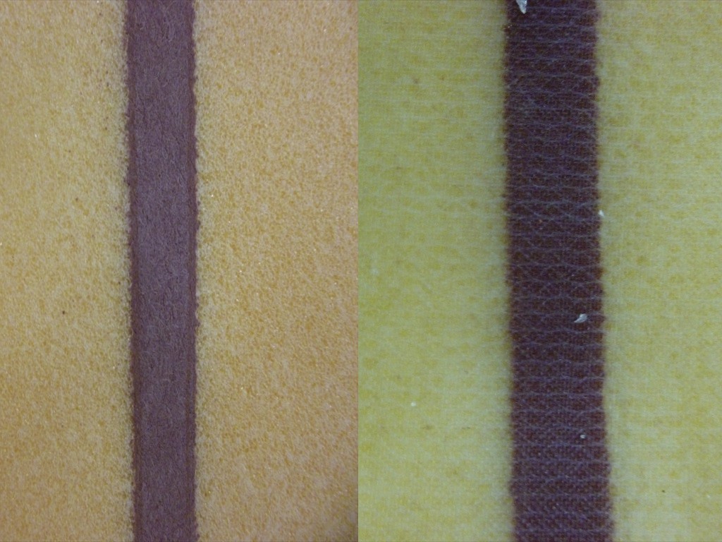
In the end, we are exceedingly satisfied with the result. Although feeling the result is more fulfilling, we try to show it.
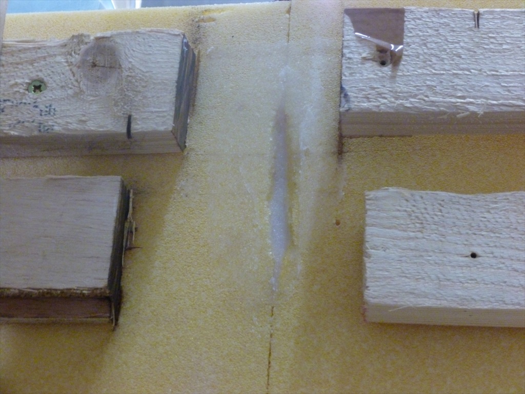
The left picture shows an untreated fragment of CoreCell, while the right picture shows a laminated (600 + 400 grams) fragment. By zooming, some small flakes of epoxy are visible.
After the portside hull we soon started with the starboard side. We only changed one method, involving the vacuum bag.
We started with placing the bag over temporary beams (protected with Compoflex waste). As soon as the bag was evenly divided over the hull, we gently pulled the beams away while the vacuum bag placed itself in a good position.
After a vacuum test, it seemed that the project was airtight at once. Well done! Again, the entire hull was laminated within two hours.
During all of our major infusion projects we create a detailed planning involving calculations for the amount of epoxy we need to prepare and the amount of epoxy that flows into the hull. There is less than a kilo epoxy discrepancy between both hulls of 65m2. We conclude that the infusion method is clean, consistent in its bonding (glass/epoxy proportion of 60%/40%), and reproducible.
On to the next stage: Creating and placing the trusses.
The post Vacuum infusion inside hull appeared first on Bouw project G-Force1500C catamaran.
]]>The post Bulkheads installed appeared first on Bouw project G-Force1500C catamaran.
]]>Now that the inside of the hull is laminated we can place the previously made bulkheads. This provides extra security on the inside when rotating the hull. On the outside of the hull fiberglass mats need to be added aswel in order to reach full strength and structural integrity.
Some bulkheads became too big to saw out of one panel. The bulkheads made out of 2 panels are first being glued together. This is done by attaching the parts together and adding a mixture of epoxy and aerosil, place this mixture under pressure until it is fully hardened.
To realize the full sturdiness the glue strip will hold another strip of fiberglass mats with the exact same weight as the fiberglass mat on the truss. On a piece of plastic we will roll the strips first through the epoxy mix so that the strip is fully drenched. We leave them to dry for a bit and then apply on the seam. On top of that we will place a strip of peelpy; also drenched in epoxy. The peelply is removed after hardening, this leaves us with a nice and even surface. The piece of baking paper underneath the truss ensures that the truss does not stick to anything.
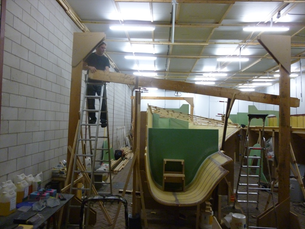
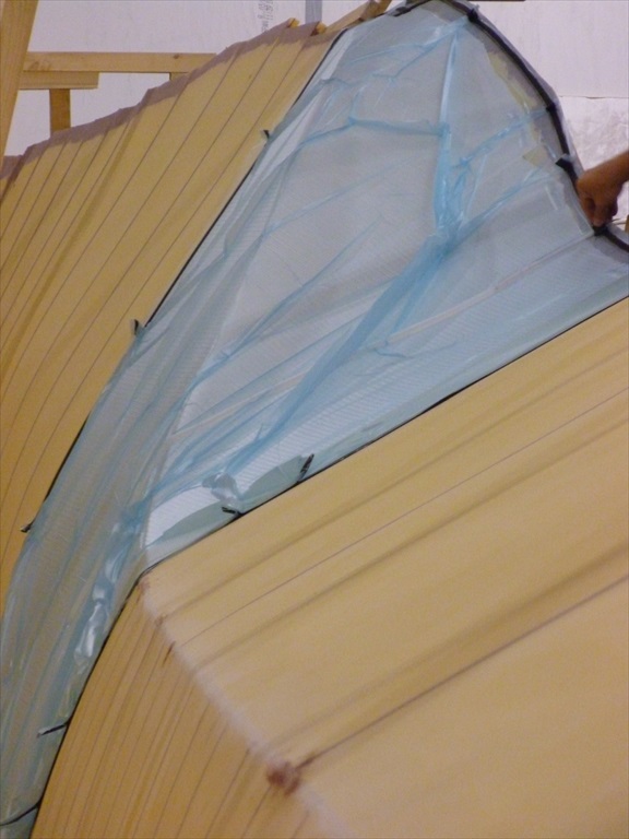
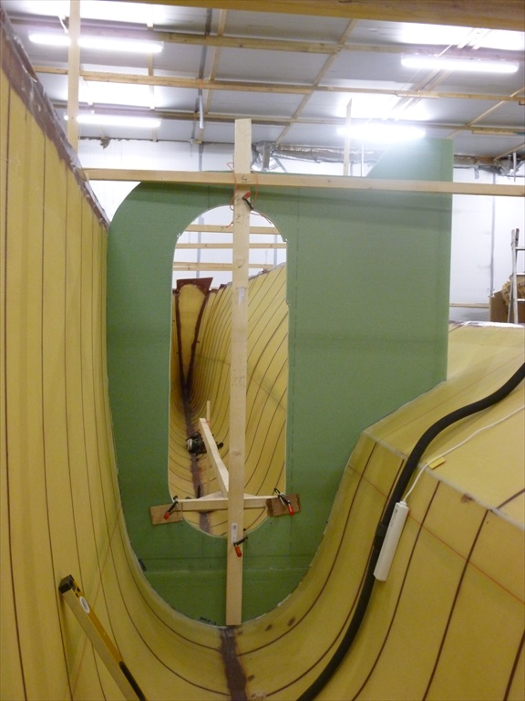
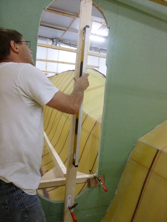
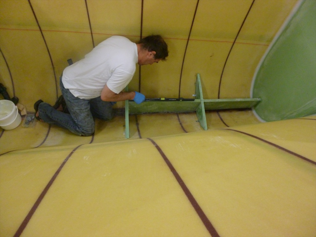
Aligning the bulkheads
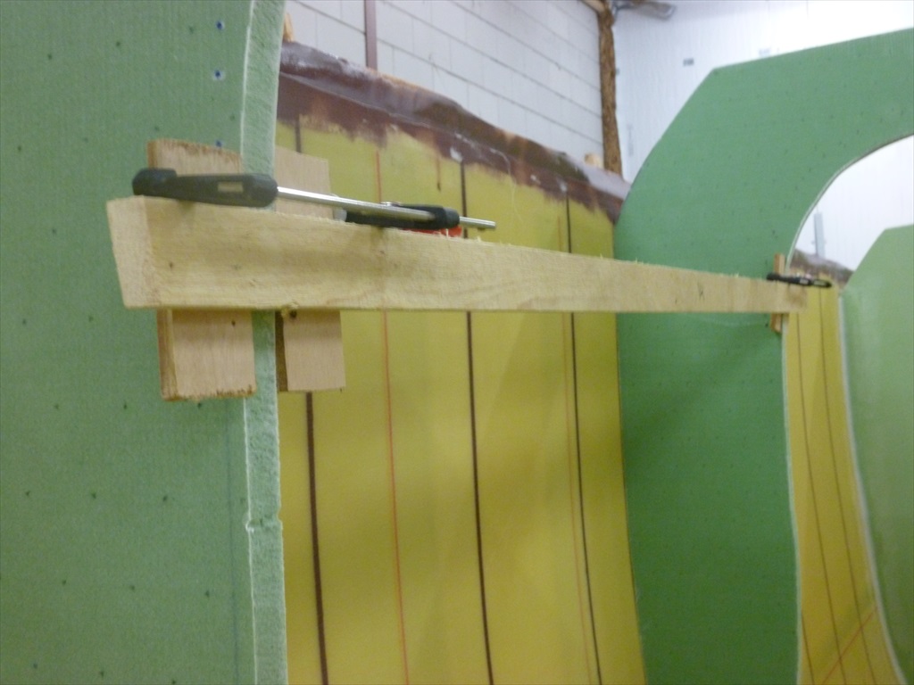
The first truss is always the trickiest. In the beginning you lack a referencing framework. All resources are being tapped, Battens in the direction of the truss (we already marked the centreline and the waterline) and a long batten on top of the keel beam with a perpendicular line. After 15 minutes it is exactly the way we wanted.
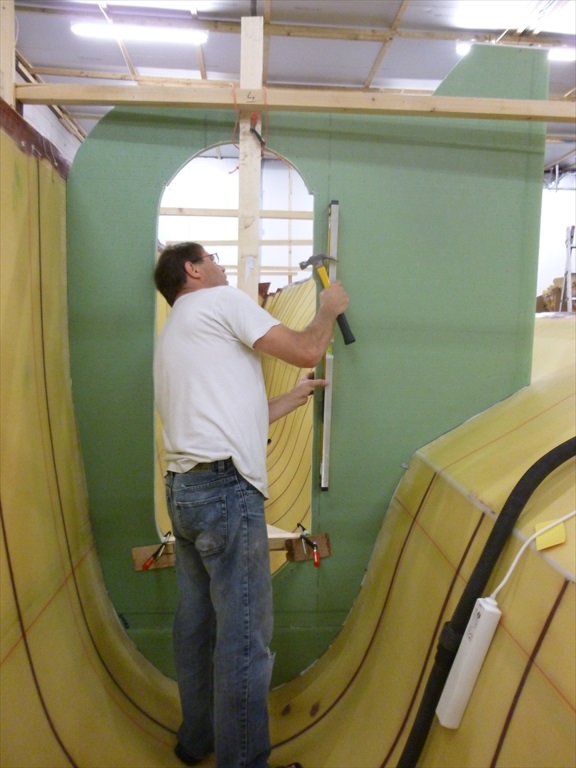
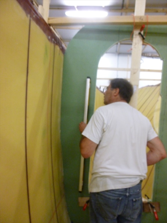
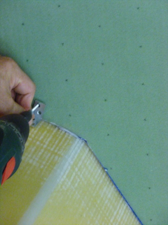
Now that we know how the bulkhead has to be placed we will place temporary small brackets on the hull. Then we can remove them to add glue on sanded part. The epoxy with aerosol is being placed in a candy bag (like the chefs in a restaurant do with whip cream) to add a nice even and broad strip of glue on the hull. After that we pressed the bulkhead firmly in the glue and we secured it with the small brackets. Leftover epoxy is removed before it is fully hardend. Naturally we checked the alignment again before the placement of the bulkhead.

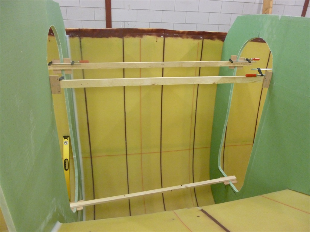
Bulkhead 5 was our benchmark. From there we measured the bulkhead from front to back. To measure the distance between bulkhead 6 and 4 we made 3 identical wooden beams. These wooden beams were secured in the doorway. This served an additional purpose as the alignment was made more easy.
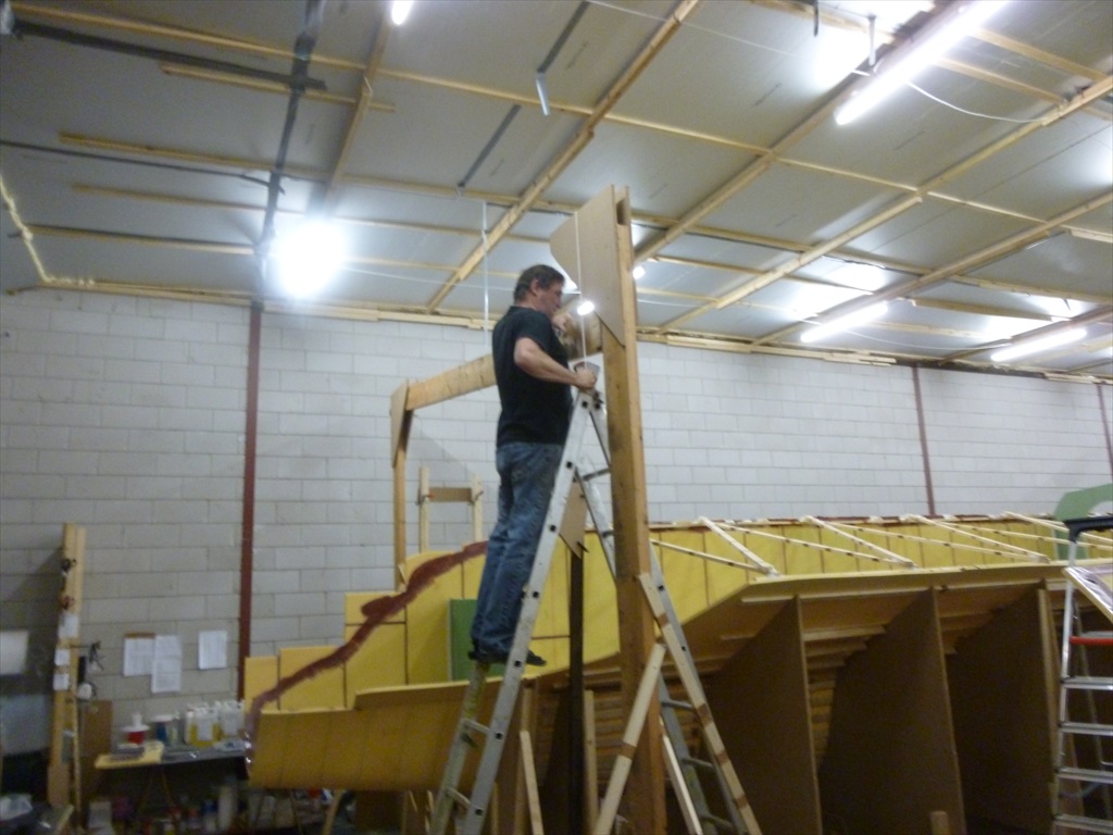
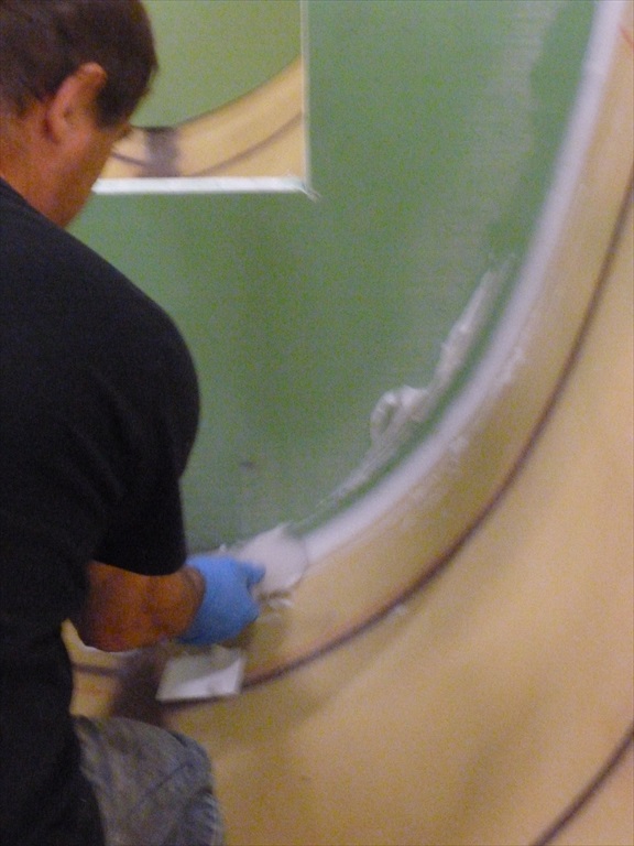
Fillets in the seams
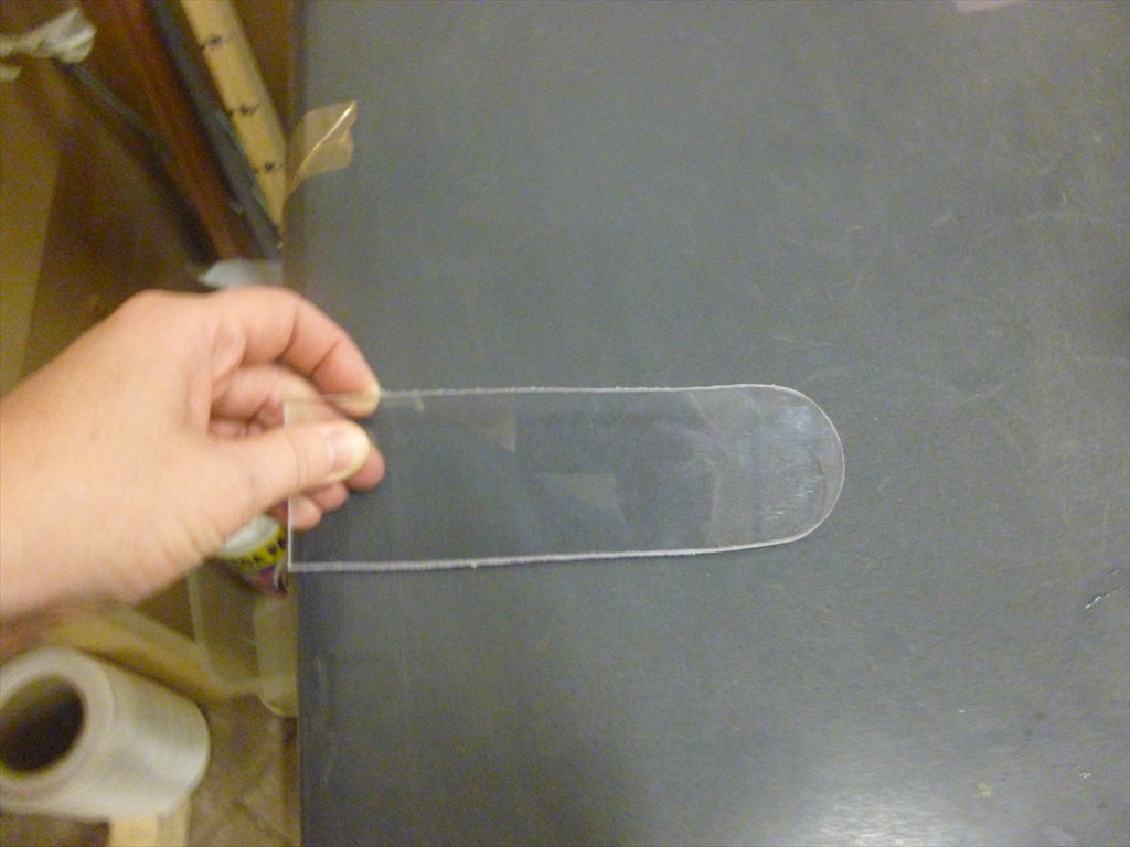
Now that the bulkheads are in place they will receive on both ends a fillet with a radius of 25 mm. Again we made an additional aid that ensured an easy applying process for the filet. An old piece of lexaan from the previous build was used here. Firm enough, easy to shape with the jig saw and the eccentric sander and after use, easily cleaned.
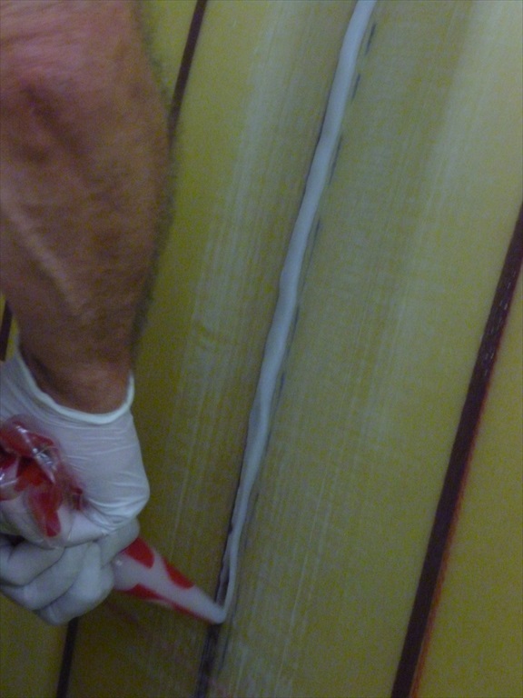
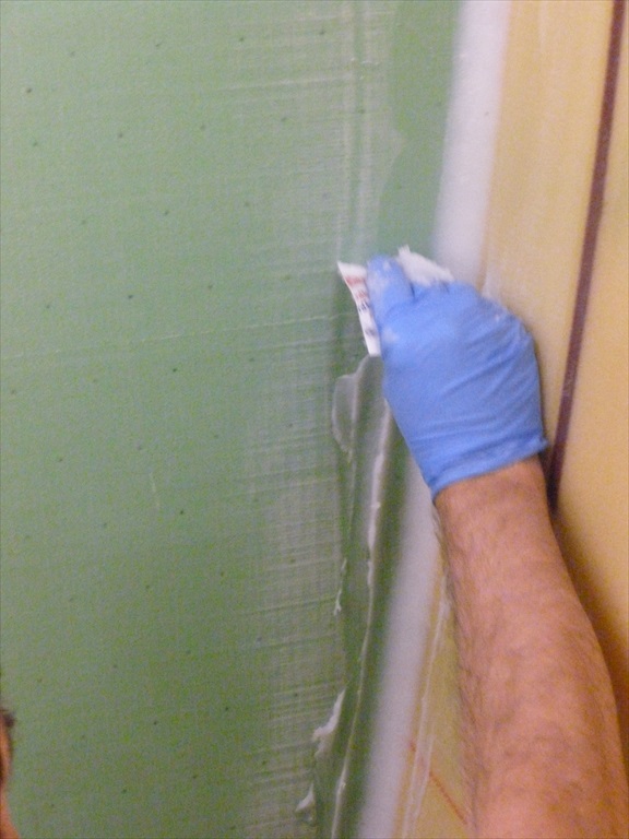
First we apply a layer of epoxy mixed with aerosol and cotton, with a formed spatula we made a nice smooth filet and the residue epoxy was immediately removed so we could keep a smooth surface. Later we will place additional strips of fiberglass mats for maximum strength.
Underfloor web
After the bulkheads the web underneath the floor up for treatment. Working this way leaves us with even additional strength for the turning of the hull. Because they are allot smaller it is much easier to align and glue. Laying fillets is harder because you need to put your feet somewhere while working (preferably not in a fresh and nice epoxy seamJ )On these parts the floor will be placed, in the end you will stand around 20 centimetre underneath the waterline.
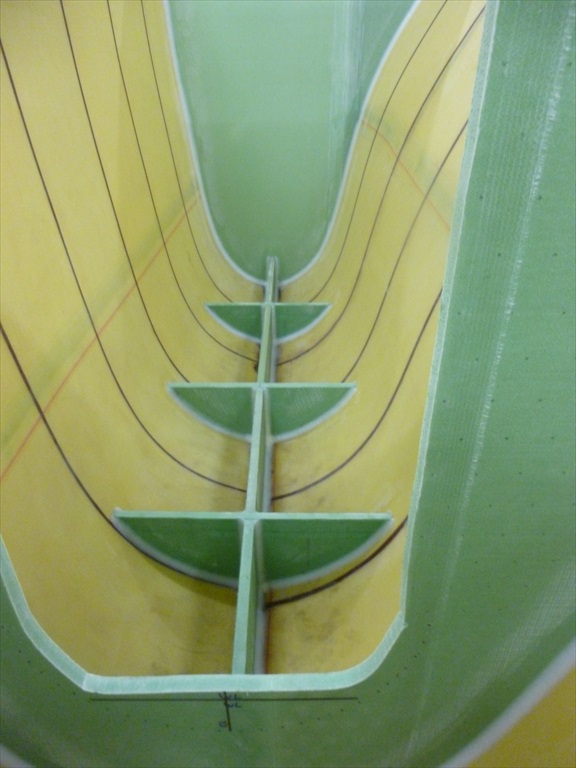
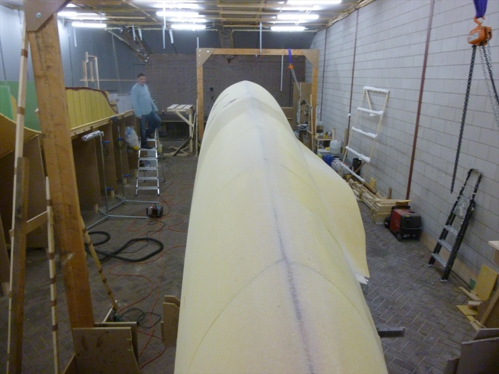
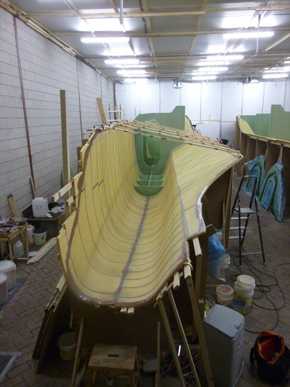
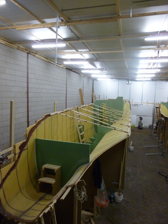
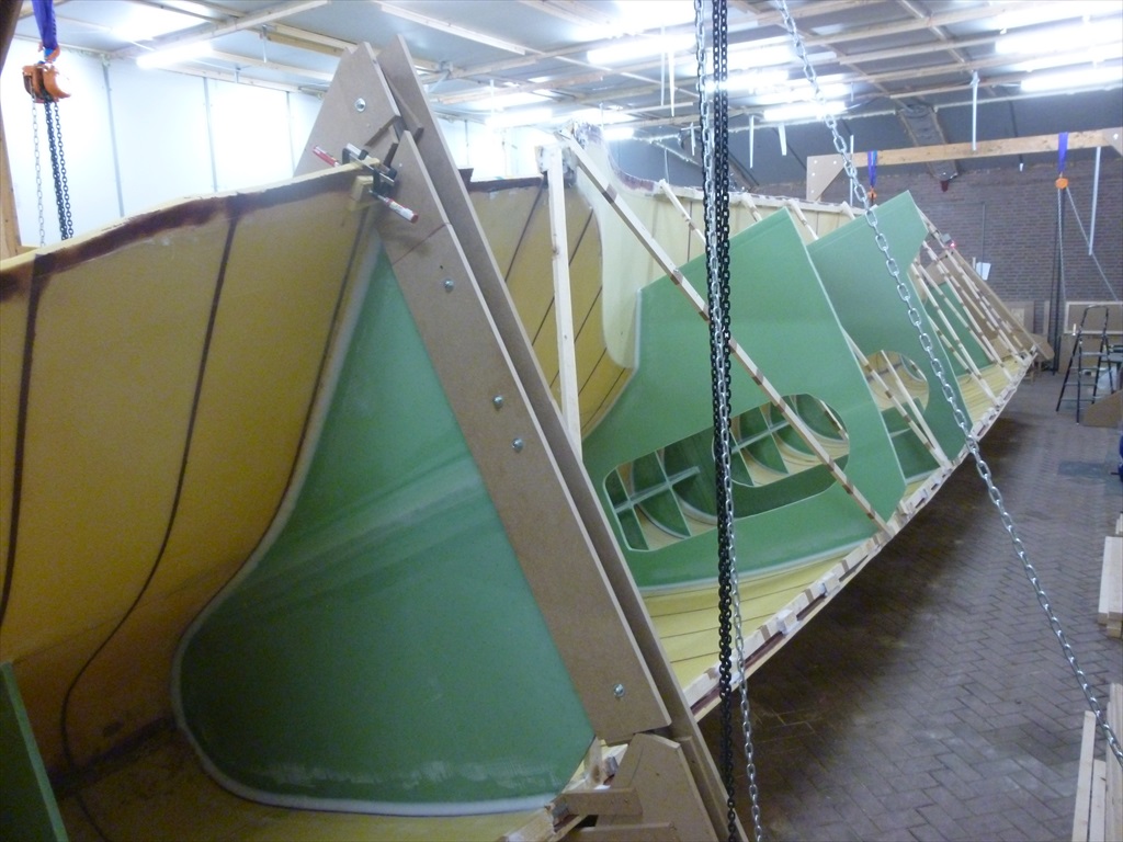
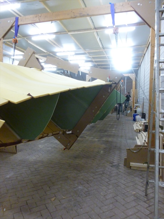
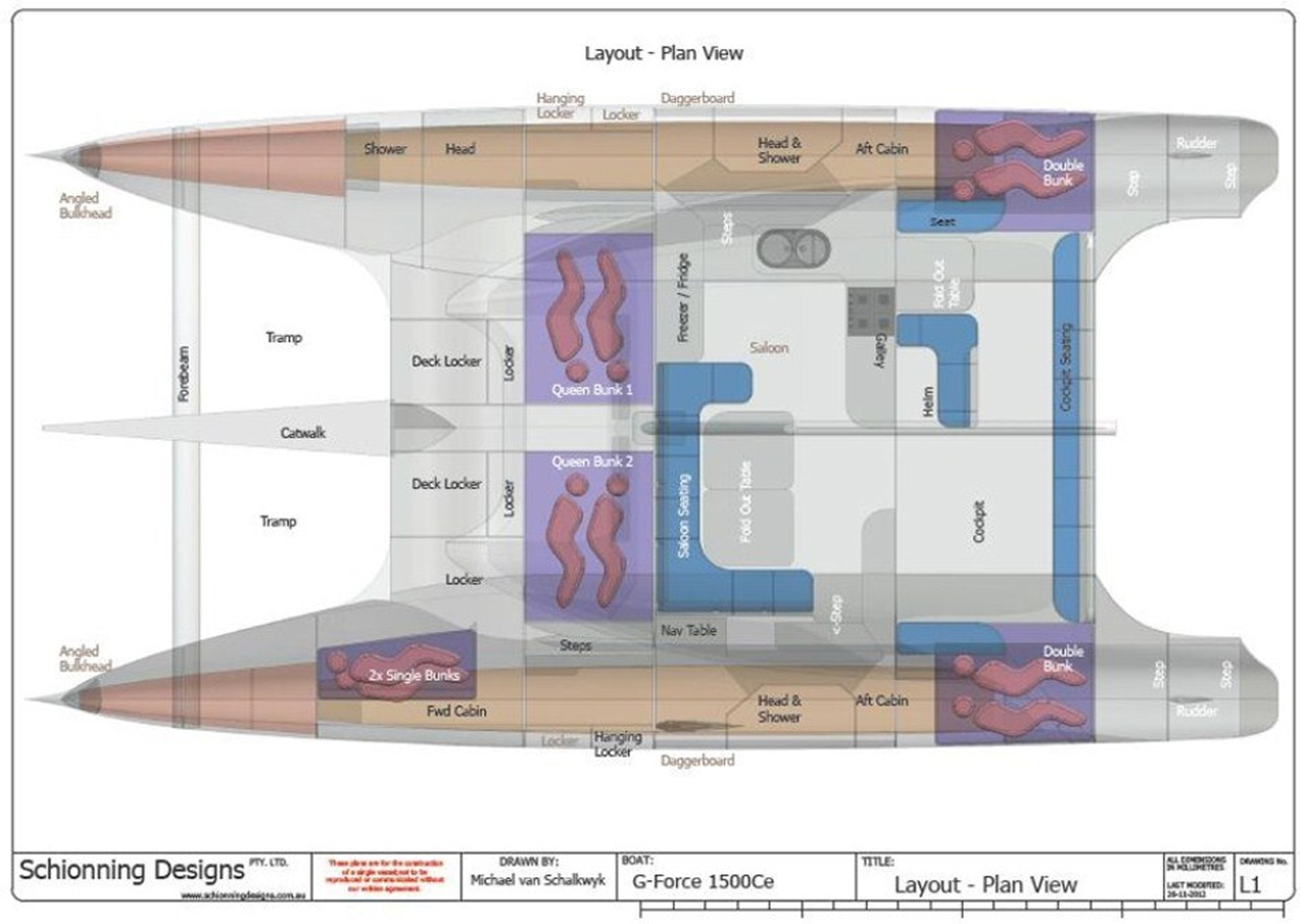
It is starting to get its form. Left: one truss more. Here will be our shower/washing and toilet cabin. Right: (closed truss) here will be a cabin with a bunk bed.
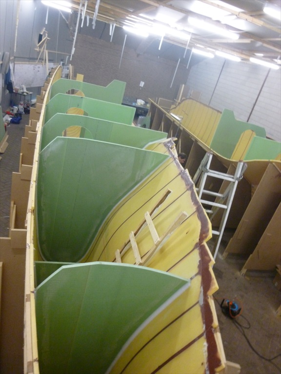
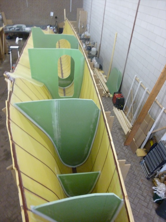
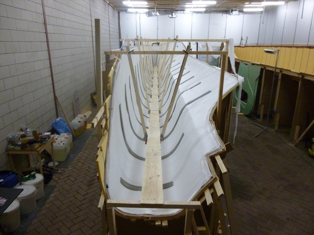
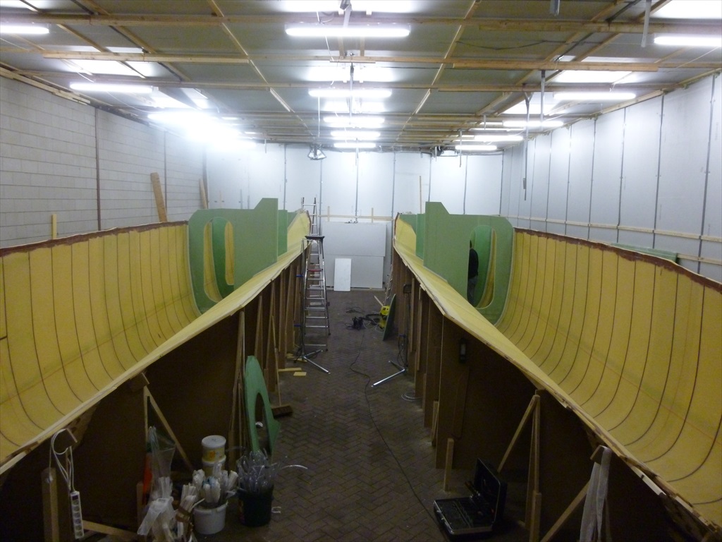
Above you see the view from the front till the back. The first truss wil become the entrance to the sleeping cabines. The hulls will be 2 meters apart. Above the chamfer (the sloping side in the middle path) there will be the bridge with salon and cockpit.
Perhaps these images help shape your imagination:
The post Bulkheads installed appeared first on Bouw project G-Force1500C catamaran.
]]>The post Vacuum infusion flat panels appeared first on Bouw project G-Force1500C catamaran.
]]>There are still some finishing touches needed on the inside of the hull before we can start with reinforcing the hulls with fiberglass. First we will make the bulkheads and floor parts for the hull. This way we gain experience and practice with the theory of vacuum infusion on relatively small projects before starting the big infusion project on the whole hull.
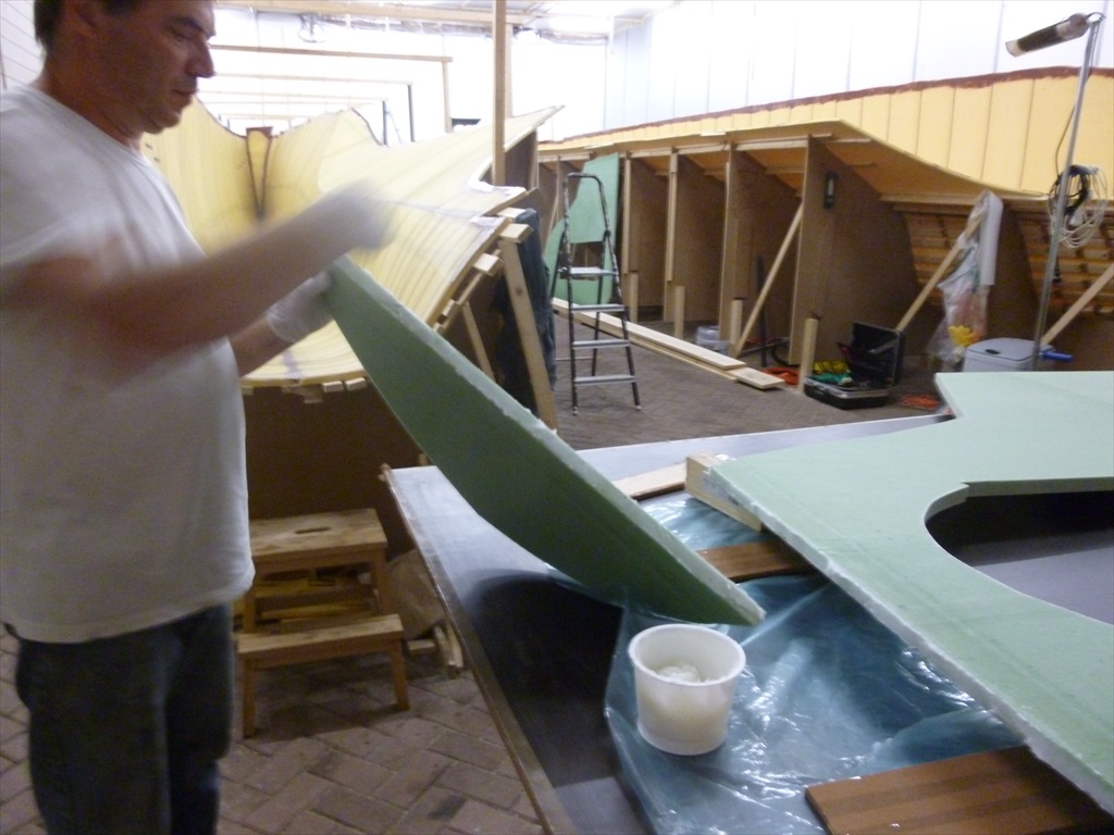
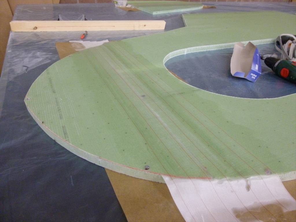
As you can see below there are plenty of parts to be fabricated.
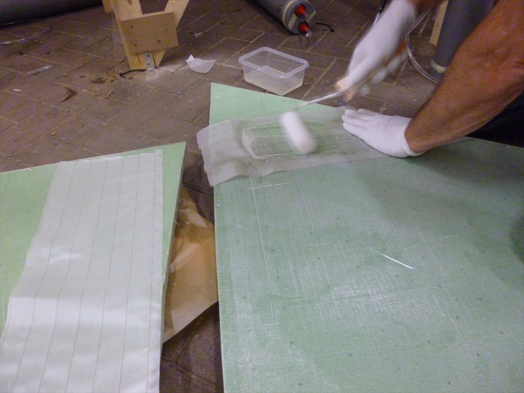
The parts will be fabricated by putting green Airex plates on two sides together and reinforcing them with fiberglass. After the epoxy has cured we can draw and saw the parts from the bigger Airex plate. By placing 2 or 3 plates together and covering them with fiberglass we save allot of preparation time and it enables us to get multiple parts from one plate. After puzzling with AutoCAD Porter has made an efficient lay-out of the parts.
The materials a bulk of epoxy and fiberglass purchased 5 months ago are finally in use, a great and special feeling, so far we have been able to work without a mess, unique considering the mess that usually goes hand in hand while working with fiberglass and epoxy. We are very satisfied with the vacuum infusion compared to the hand layup method Porter has used while building the “Double Twenty.” The preparation time is a bit longer because the fiberglass, compoflex and a vacuum bag has to be placed on the ‘glue’ table without moving the mats or puncturing the vacuum bag.

Before we begin we made a residue pipe (traps) to trap the excess of epoxy and ensure that our vacuum pump remains clean and clear of epoxy. A couple extra traps will come in handy for when the epoxy starts heating up during the process of infusion, the spares will enable us to disconnect and replace the filled traps. The traps that have become to hot will implode and become useless, therefore we will try to empty them before this happens.
The preparing of the Airex plates
To ensure the 2 Airex plates will fit smoothly we will mill a tongue and groove connection. A simple mold works easily and ensures a constant thickness. The groove is made with a standard setting so that we get the same dimensions every time.
The Airex panels have a hole pattern (perforated) that enables us to glue the fiberglass mats on both sides simultaneously.
This means that we also have to build everything in mirror image.
From top to bottom:
- Vacuum bag (will be closed with tape)
- Compoflex (temporary canvas, that enables the flow of epoxy without sticking to the fiberglass and is easily removable)
- Strip peelply (serves as a brake in order to stop the epoxy from flowing over the edge)
- Fiberglass mats
- Foam panels
- Fiberglass mats
- Strip of peelply (again closes the bag and stops the epoxy from overflowing)
- Compoflex (temporary canvas)
- Connection tubes for epoxy and the vacuum pump
- Vacuum bag
To ensure that the bottom mats are in place we tape the shape of the plates on the glue table. Now the construction can begin.
In this photo album you can see step by step build-up of the laminate. Open the 1st foto to read the comments.
Finally; the infusion process
A good preparation will save you allot of work, and with infusion this certainly deemed to be true. When you take all the right steps you will end up with an airtight package en the rest of the process will pretty much run itself. Nevertheless, during the preparation allot of things can go wrong, usually these problems are minor and are easily fixed (most of the time these are small holes in the bag that prevent a full vacuum). These quick fixes are usually done with some tape. After some trial and error we needed less quick fixes and things went more smoothly.
The first project was done with 1 centralized epoxy inlet line, the epoxy has to flow 1 meter in both left and right. We knew it would take a bit longer but this way we had the time to follow the process. The total project took us 2,5 hours, afterwards it took an additional 8 hours for the epoxy to begin “gelling”. All this time we wanted to be close while this happened.
The testing was not really in the vacuum method, but more in the time that it took to complete a project. Some adjustments were welcome, which is why we implemented the following improvements:
- Set up the project the day before and start the project the next morning
- We added one more infusion line on both the left and the right side of the central line.
- Pre-heated the epoxy to circa 30-32 degrees Celsius.
- After the infusion keeping the project on temperature with infra-red lights to speed up the gelling process.
We tested this all first on a leftover piece of CoreCell. The measures described above worked well and in less than 30 min the project was ready to start hardening. Below you will see that the resistance drops after the second line is opened and that the flow of epoxy went allot faster.
From this moment it took 30 minutes for the test project to finish. With the extra heat from the lamps the process of hardening accelerated. The temperatures in the summer also helped out and therefore enabling to ‘unpack’ the project the next day. Sometimes the bottom of the project took a while longer and it needed some more time before removing the compoflex. Off to the preparations for the next project!
Eventually this became our favourite set up for flat panels:

In this clip you can see how a project goes and the flow of epoxy.
Laminate flat panels with vacuum infusion method
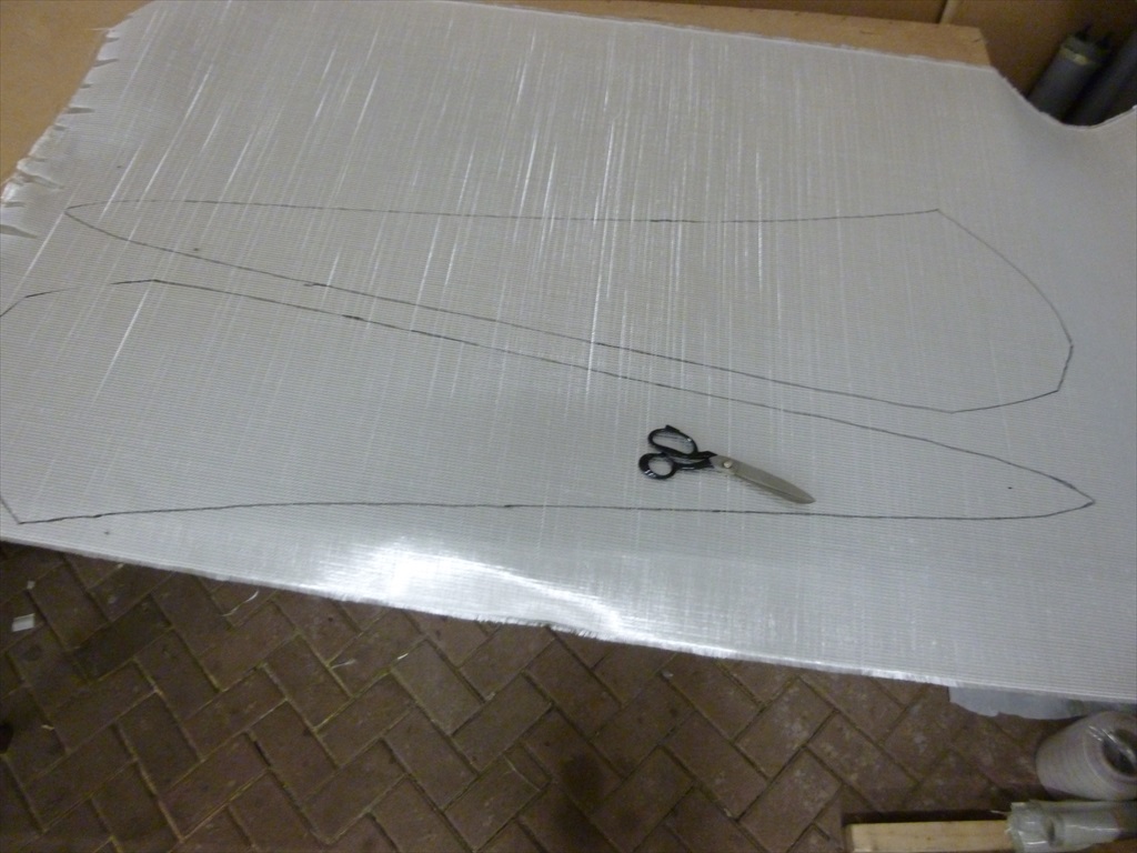
After 2 projects we got the hang of it. Porter was preparing the glue table for the next project. Lora made the blueprint for drawing and cutting out the parts from the finished projects. This worked just as easy as with the construction molds. Printing on an A0 plotter, copying the lines with a hammer and nails and redrawing it with a marker, after sawing even out the rough edges with an eccentric sander.
The post Vacuum infusion flat panels appeared first on Bouw project G-Force1500C catamaran.
]]>The post Micro-balloons filling and sanding the seams appeared first on Bouw project G-Force1500C catamaran.
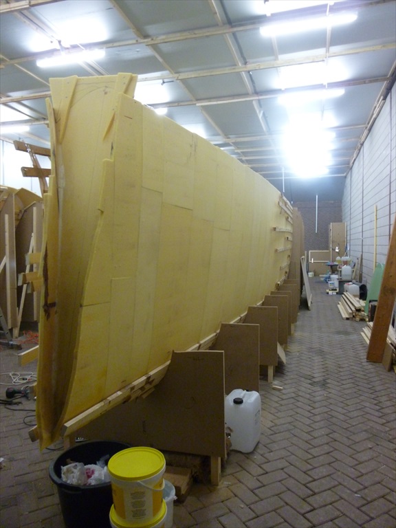
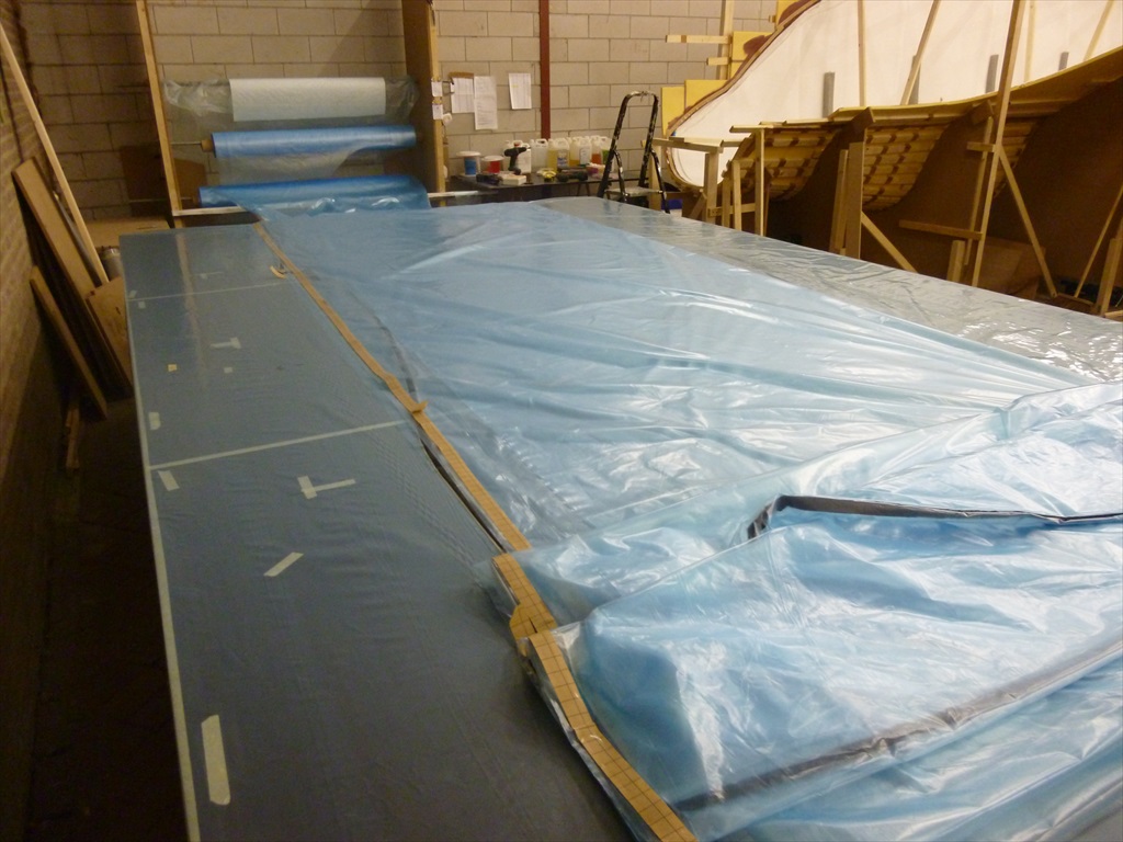
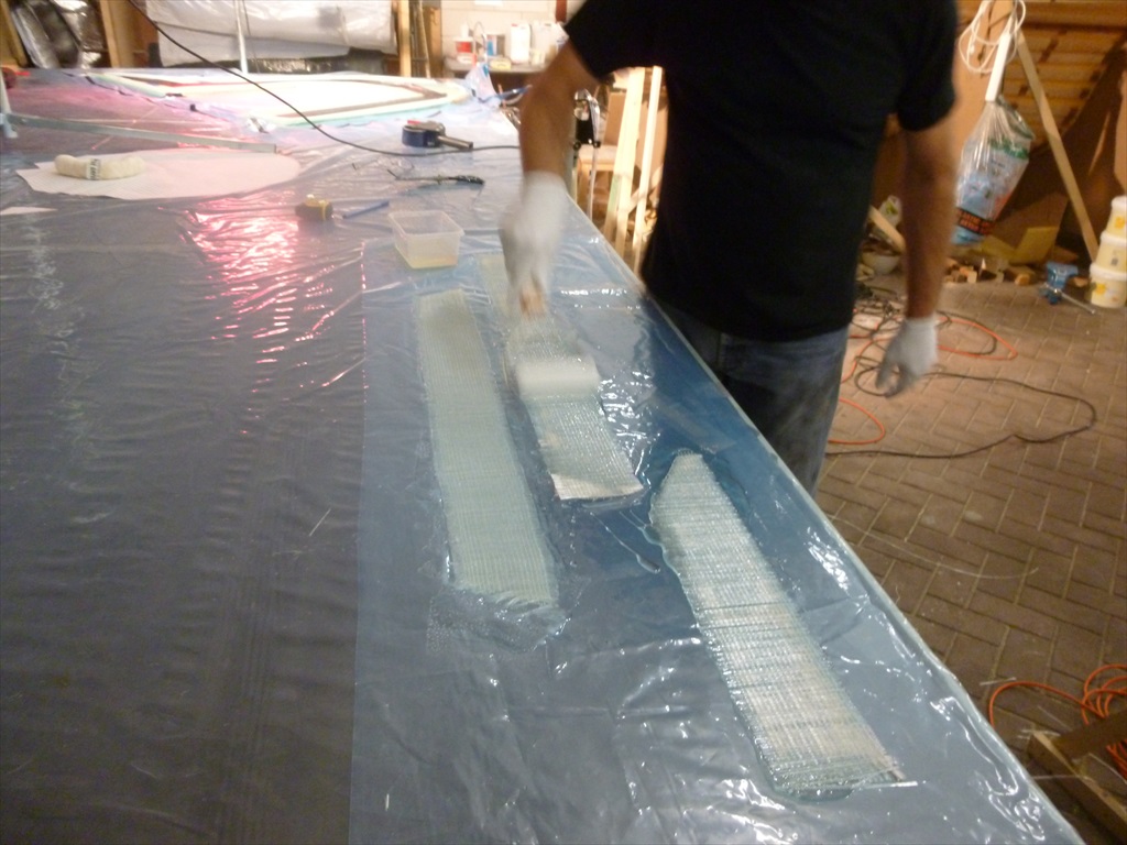
]]>After insulating our shed we made ourselves a large, flat work table. This 3m x 4m table is large enough to clad three or four foam panels with fibre-glass at a time. We will eventually cut components such as frames and internal doors from these large vacuum infused panels.
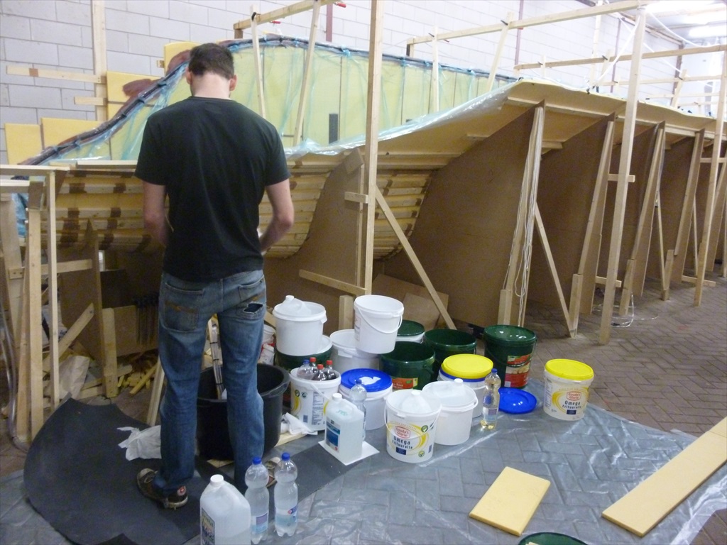
Filling the Seams with Epoxy and Micro-balloons.
In March, we started heating our newly insulated shed with electric heaters. It is not only more comfortable to work in, but also necessary for working with a Epoxy and Micro-balloon mix. The hull has to be made air tight before cladding with fibre-glass using vacuum infusion. CoreCell is inherently air tight, but not the seams, these have to be filled and sanded first.
Lora spent a good half an hour sawing up off-cuts of MDF into mixing sticks. We had already accumulated a stockpile of old yoghurt and sauce pots for mixing up the epoxy, we had cut up the lids to make nice, flexible scrapers that are perfect for getting deep down into the seams. Once mixed, the epoxy is only good for approximately half an hour, so to avoid wastage, we made lots of small batches.
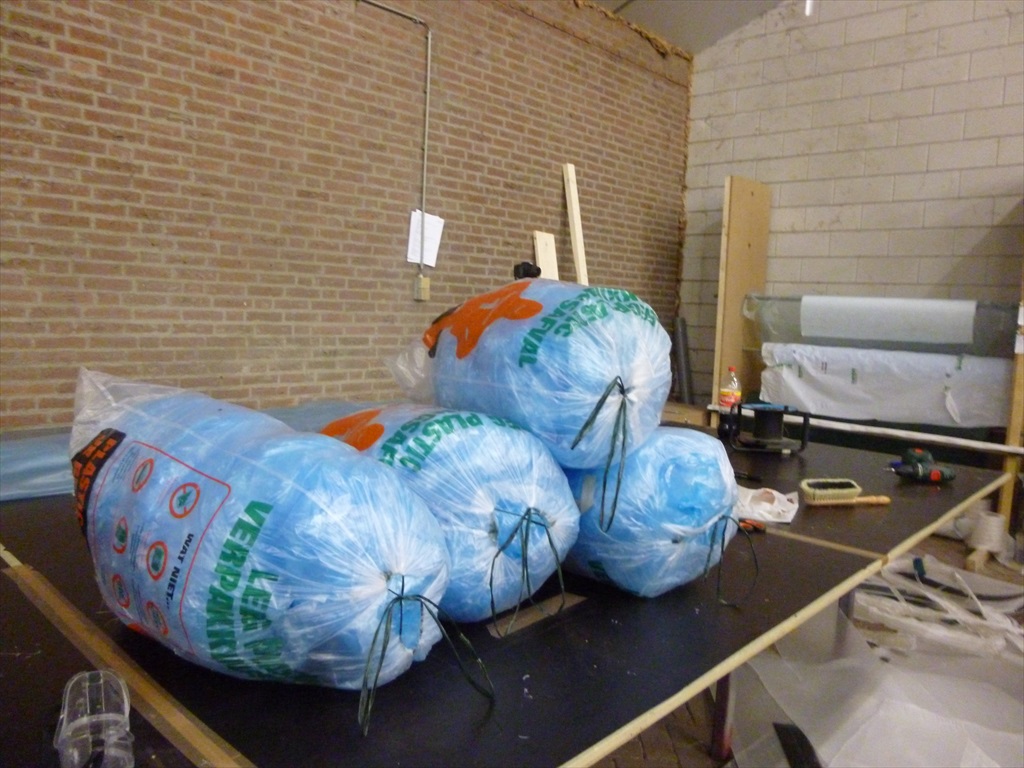
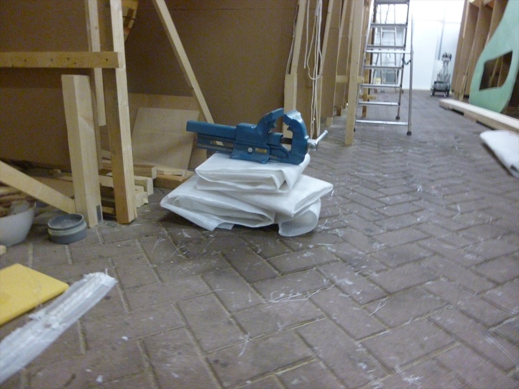
In the next two to three years we expect to use hundreds of plastic pots (see below). If you have any laying around, they will always be welcome here. You can take the opportunity to nose-around our project as well.
To make the epoxy/micro-ballon mix, first mix the epoxy and hardener, a little bit of Aerosil will improve its gluing properties. Then add in the micro-balloons. Micro-Balloons keep the paste light whilst adding volume. The final mix resembles a large pot of Chocolate Paste. According to the Micro-Balloon instructions, the red powder is better for sanding than the white, so we took the manufacturers advice and didn’t do any tests first.
Mixing Micro-balloons
Just like using any other kind of filler, there is always a risk of getting air bubbles in the seam. Air bubbles can provide a path for false air when a vacuum is being generated, so to prevent this, we filled in three layers.
To fill the seams, push the first layer deep into the seam, remove any over-spill on the panels straight away. Apply the second layer within twenty-four hours, but do not fill the seam completely, once again, remove over-spill from the panels immediately. The final layer should be applied royally, once hardened, the excess can be sanded down using an orbital sander and will leave a perfectly smooth finish.
Bringing on the following layer within twenty-four hours of the previous one means it will have a good surface to bond to without having to key the previous layer first. We planned our work in such a way that we were able to fill for three days in a row without having to sand or rub-down.
We are glad we initially only installed the slats on the outside of the mould leaving the inside free accessible. We have full access to the surface of the hull without damaging the foam.
The Inner Hull walls
Once the outer walls of the hulls were foamed, filled and sanded, we were able to start on the inner walls.
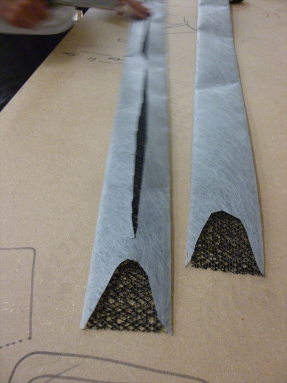
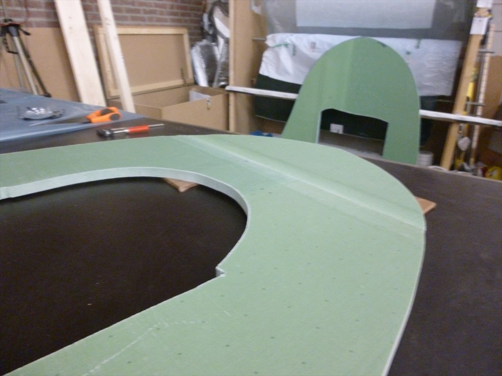
The chamfer panel forms a 45 degree joint between the hull and the bridge deck. The chamfer panel has a complex shape, so we allowed for this by leaving material protruding out. This excess will be removed at a later date once the chamfer has been shaped properly.
Working in the bow area was not easy, there is a limited amount of space to work in and the panels have to bend in two directions. To make shaping easier we used 20cm panels instead of the 40cm used on the rest of the hull.
To prevent damage to the foam when walking back and forth to the work area, we removed our shoes and worked in socks only.
The stern extends 20cm past the last frame. So to ensure the slats were aligned properly we made and fitted a temporary tail-board, then fitted supports to secure them in place. These supports are fixed to the ground. Once happy with the shape, we were able to continue with filling and sanding.
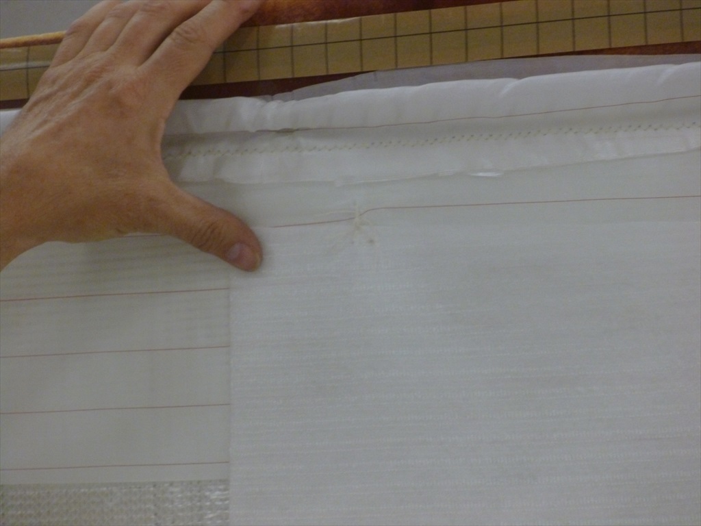
Preparing the 10.5m long chamfer panels made a nice change. We temporarily fixed the panels edge to edge and marked the joint. These reference marks will come in handy later when we lay the panel into the mould. To aid shaping of the chamfer panel, Porter divided the template drawing into 1m sections and printed them out on the plotter at a scale of 1:1, joined them up and laid them on top of the panels. He was then able to quickly and accurately transfer the shape to the panel. A piece of cake!
Material for the frames and vacuum infusion have already been ordered. It looks like we will be able to lay-up the first glass-fibre mats in the last week of June. We will use these frames as tests to perfect vacuum infusion before moving onto the hulls.
The post Micro-balloons filling and sanding the seams appeared first on Bouw project G-Force1500C catamaran.
]]>The post Frames and thermoforming appeared first on Bouw project G-Force1500C catamaran.
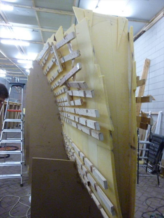
]]>Battens and Frames
As you might already have read in the ‘Building Method’ section, after positioning the frames, the longitudinal wooden battens then have to be fitted. These battens will enable us to form, shape and fasten the foam panels. Because we are using a female jig, we had to take into account the 20mm thickness of the battens by adding 20mm to the frame profiles.
The distance between the frames varies between 50cm and 100cm. The battens we used are 420cm long, the long length gave us the advantage of being able to bridge four frames at a time, thus giving us a nice, smooth curve. There are also fewer joints to make between the battens-ends.
The first step was to accurately fix battens left and right of the Center line and along the complete length of the keel. The Center line previously been marked out on the floor before position the frames. These two battens together form the keel, the backbone of the hull.
Schionning designed the G-Force 1500C with the home builder in mind. The hull above the water line is fairly straight compared to that below the waterline. This means the foam will be easier to shape and require less support. Battens above the water line could therefore be placed further apart. The hull below the water line is heavily curved, so the panels require more support, we therefore had to mount the battens much closer together. Joining the battens is easy and doesn’t take long. It is however, important to make sure that they follow the profile of the hull; this will prevent bulges in the finished hull.
The bow requires the most attention
The bow was very tricky to lay-up because of the extreme compound curves. The hull bends round not only lengthwise, but also in height. Our 20mm battens are simply not flexible enough to follow these curves. This problem was solved by laminating two 9mm thick multiplex slats and bonding them to form a single batten. The missing 2mm was filled with a thin wooden strip.
The outside of the hull will be foam stripped first. To make access easier, any internal battens will be fitted at a later date.
In mid/January we reached a milestone:
the two hulls were ready for installing the foam.
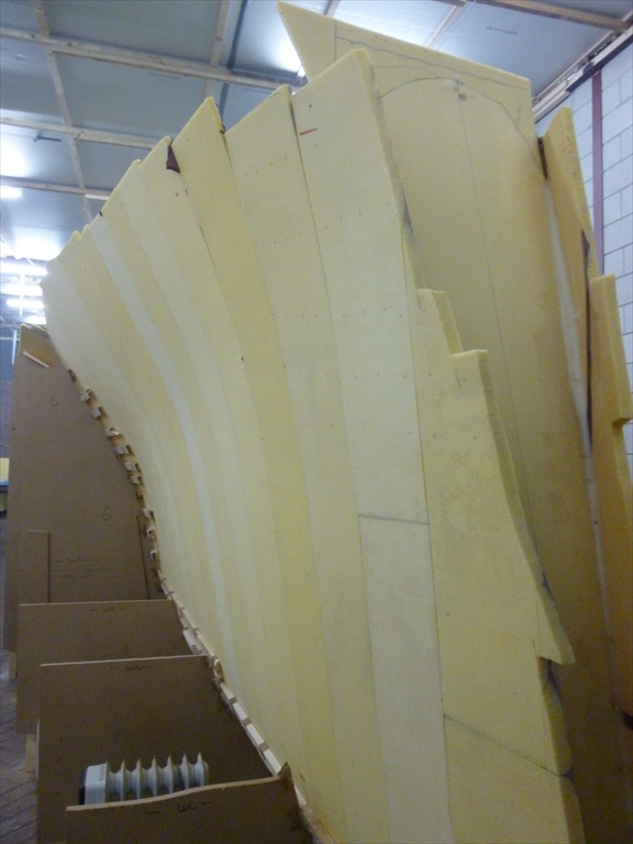
Working with Corecell, a nice challenge.
This is the first time that we’ve worked with foam, we did however do a lot of research beforehand. We decided to use as wide a panel as possible; this will reduce the number of seams in the hull and also reduce the chance of air leakage (see the section on ‘Building Method’).
Our ‘CoreCell’ panels were originally 122cm wide by 244cm long. Using a circular saw, we cut each panel into three narrower strips each 40.5cm wide and finished the strips off by chamfering the edges to 45° with an electric Router. Chamfering the edges makes filling the seams a lot easier.
Forming the Corecell foam panelsrengen
CoreCell foam is easier to form when warm. The optimum temperature for forming is about 60°C. Henny (www.fram.nl) suggested we use a hot air paint stripper as a heat source. He said it would work up to a width of about 40cm, and that it would take a little practice, probably 6 panels or so, to get a ‘feel for it’.
The first panel went well, but was very tricky. The problem was getting the right amount of heat into the panel and keeping it there without causing local overheating. Foam cools off quite quickly and the panel loses its flexibility. Porter decided to see if he could find a way of improving the technique.
When Henny built his boat he used 16mm CoreCell panels, ours are 20mm. His panels needed less heat. One possible solution was to reduce the panel width to 30cm, but that meant having more seams. After a bit of head-scratching Porter decided to use two hot air guns mounted in a simple wooden frame. He was then able to introduce more heat and cover a greater area in one pass. After four or five panels using the new, improved double hot air gun we had it down to a tee.
Foam that has been formed should be kept in place while it cools. We temporarily held the panels in place using wooden slats that were themselves either screwed or clamped. The foam panel was then fastened to the battens from the outside using self-tapping wood screws.
It was nice to be able to work for so long without using a drop of epoxy. This is definitely one of the advantages of this method of construction.
We started laying-up by placing the first panel roughly in the middle of the hull where it’s less curved. The next panel was placed to the left of that panel and the second to the right, slowly working our way out towards the bow and stern.
We developed an efficient routine. Porter first formed and clamped a panel, then moved on to the next; at the same time Lora ran a line of tape over the battens down what would become the seam for Pauls’ next panel. She then moved on to fixing Paul’s previous panel from the outside, always staying one panel behind Paul. The forming and clamping, and fastening and taping activities took about the same time, so we were able to work perfectly in sync.
The tape forms a non-stick barrier between the seams and the wooden battens, protecting the battens from any leaking resin.
We found ourselves having to modify the panels slightly as we got closer to the more curved bow and stern. This slight re-shaping along one edge was necessary to keep the panels vertical and maintain a good fit. At the bow and stern the curves became so extreme that we were unable to form the 40cm panels, we had no option but to use much narrower, shorter strips.
Once we got used to working with foam we were able to work quite fast. Laying-up the foam panels took all-in-all about 90 hours.
You can see a slideshow showing step for step how we did it in the “How do you do it” section.
Timelaps thermoforming de foam panelen in de romp
Cold, cold and even colder.
We were hoping for a mild winter this year, but temperatures have been hovering around freezing for a long time now. Our plan was to have the starboard hull ready for filling the seams now, but it’s been too cold. The resin/micro-balloons mixture used to for the beading can only be used above 10°C and to do the epoxy infusion we need temperatures of at least 18°C. Final curing of the hulls will require heating them to 50°C for approximately 24 hours. This seemed like a good time to invest in thermal insulation for the workshop. Insulating the workshop would be a project on its own. We finally managed to install insulation panels over the 10mx20m work floor without using additional vertical supports. Any supports that we added would get in the way of the hulls.
With the insulation in place we can now concentrate with the task of building a boat.
The post Frames and thermoforming appeared first on Bouw project G-Force1500C catamaran.
]]>The post Building frames appeared first on Bouw project G-Force1500C catamaran.
]]>The design that we bought from Schionning was so new that we had to wait while the first set of drawings were being scrutinised for CE approval.
Scale Mode
We made use of that time by going ahead with preparations for the build. We also took the opportunity to make a scale model of the jigs for the port and starboard hulls.
These models turned out to be very useful, giving us a good idea of what the final jigs will look like. After studying the models for a while we decided that some frames looked a little weak around the outside, and that others needed strengthening at the bottom. Based on our new insight, we decided to modify the frames by adding an extra 10cm around the outside edges and strengthen others where we felt it necessary. We were able to do all this with our available stock of forty MDF panels.
It became clear to us that Schionning had put a lot of thought into their design, and how to build it. Where possible, parts have been designed with straight edges. This allows us to make efficient use of our building materials.
Building frames
As you’ve may have already read by buildingmethod we decided earlier in the planning phase to work with a female jig instead of a male jig. A female jig will enable us to screw the slats directly into the frame profiles. The drawings made by Schionning are of male jig sections. Porter spent a few hours modifying the original frame sections in AutoCAD. He basically subtracted the height of the slats from the frame profiles, only a few centimetres in all, but it insured that we can build the remaining boat sections without having to modify them first.
We have to use three datum lines in order to accurately position the frames: the Waterline, the Centreline and the Deck-line. These were all clearly marked on each of the frames. There are eighteen frames per hull, many of which are made up of three pieces. We had to cut out eighty-six parts in all.
Porter designed a cutting plan that allowed us to cut all the pieces out of our MDF panels with as little waste as possible. We did consider having the pieces cut professionally using a computer controlled laser-cutter or router, but in the end decided to do it ourselves. This is where our A0-plotter came into its own.
On Friday 7 December all the materials necessary for the jigs had been delivered. Full of enthusiasm, we made a start.
Take a look in our photo album at facebook.
Alternatively, look at our photo compilation on YouTube
Using A0 size prints from our plotter, we were easily able to transpose drawings onto the MDF panels. It was tempting to trace around the cut-outs from the port hull and use these as a template for the starboard hull. It would appear to be a lot faster this way, but if you make a mistake, you’ll have two parts to re-do instead of one.
There are only a few small differences between the port and starboard jigs, but if you saw the frames in one go you know exactly what to look out for and the job goes quite quickly.
After three or four evenings Lora had managed to transpose all the frame drawings onto the MDF boards and Porter had already sawn a few out.
When not jig-sawing, Porter spent time experimenting, trying to find the best way to assemble the frames, it was also a good opportunity to see if our plan was working.
Spending hours lugging large MDF cut-outs around, getting down on your knees to assemble them and then moving the completed, full size frames around is absolutely exhausting. It’s a nice thought knowing that this will not last for forever, and that in just a few days we will be able to start working with luxurious, light and easy to handle foam.
Whilst assembling the frames, we took the opportunity to strengthen the weak looking areas fit legs. We also fitted temporary battens to keep the frames in shape.
Aligning and rigging the building frames
Whenever we’re busy working away on our boat, tended to find ourselves drifting off and thinking ahead to the next steps. It is this curiosity that becomes the driving force in the build and keeps the pace up. Hopefully we’ll never lose this drive.
After completing a few frames it was clear that our plan was working well. We decided to finish the remaining frames together at a later date, but first we wanted to make a start on assembling the starboard jig.
Following the positioning of frame 1 comes the positioning of frames 2 to 18.
Starting with the stern as a reference, each frame had to be accurately positioned in all three planes, and relative to each other.
The final position of each frame was then marked on the floor. The whole process took a lot of time, the first few seemed to take forever, but it’s well worth taking your time and working accurately.
This is what we managed to achieve in the first month of building:
In January. . .
We’ll start fitting the slats; these will form the base for the foam layer. By the end of the month we hope to have a fully foam-clad hull.
The post Building frames appeared first on Bouw project G-Force1500C catamaran.
]]>